The Inductor Model Extractor (IME) feature is only available if you have purchased a Broadband Spice Extractor license from Sonnet. Please see your system administrator if you are unsure of the availability of this feature.
The Inductor Model Extractor (IME) feature allows you to extract an intuitive equivalent circuit model from the EM analysis of a spiral inductor.
Model Topologies
There are two topologies available for the Inductor model: the “Untapped” model and the “Center Tapped” model. Both topologies generate a simple, physical, fixed-topology circuit model.
Untapped Topology
Shown below is the schematic of the “Untapped” inductor model topology.
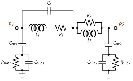
The Untapped model is appropriate under the following conditions:
- The inductor must have at least two ports. Ports 1 and 2 must be the input/output ports of the inductor. If you include any additional ports, the algorithm assumes that you will be connecting them to ground in your circuit simulator. Thus, you may connect ports to a patterned ground shield or ground ring if you wish.
- The analysis frequency band should extend from the frequency where Q exceeds unity to approximately twice the frequency at which the maximum Q-factor is found.
- This model extraction technique has proven most effective with spiral inductors on a conductive substrate, such as those usually found in RFIC processes involving lossy silicon substrates.
Center Tapped Topology
Shown below is the schematic of the “Center Tapped” inductor model topology.
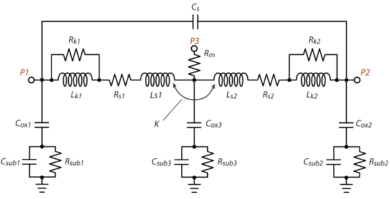
The Center Tapped model is appropriate under the following conditions:
- The inductor must have at least three ports. Ports 1 and 2 must be the input/output ports, and port 3 must be the center-tap port. If you include any additional ports, the algorithm assumes that you will be connecting them to ground in your circuit simulator. Thus, you may connect ports to a patterned ground shield or ground ring if you wish.
- The analysis frequency band must include the frequency where Q is maximum. In addition, it is recommended to do a wideband sweep to improve the model performance. Since this topology is not meant to be used above the self-resonance frequency, any data above the self-resonance frequency is ignored by the extraction algorithm.
- This model extraction technique has proven most effective with spiral inductors on a conductive substrate, such as those usually found in RFIC processes involving lossy silicon substrates
Model Output
When the model is extracted, a netlist with the specified topology is written. The format of the netlist can be Spectre, PSpice, or Sonnet Netlist, and is specified when setting up your output file. You also have the option of requesting a Touchstone file with the s-parameter response of the extracted model. For more details, please see below.
Using the Inductor Model Extractor (IME)
You have two options of when to create this model. You may specify an output file in the project editor before your analysis, so that the inductor model output file is created automatically at the end of your analysis. It is also possible to create the output file after the analysis is complete when looking at your analysis response data in the response viewer. The method used in the project editor is detailed below.
NOTE: At the time of printing, the ability to create an inductor model was only available in the project editor.
Using the IME in the Project Editor
To setup your output file so that it is automatically generated as part of your EM analysis, do the following:
- Open the desired project in the project editor.
- Select Circuit ⇒Settings from the project editor main menu.
The Circuit Settings dialog box appears on your display.
- If it is not already selected, click on Output Files in the Sidebar menu of the Circuit Settings dialog box.
The appearance of the dialog box is updated to display the Output File page.
- ..Click on the Add File button in the Output File page and select Inductor Model from the drop down menu.
The Inductor Model File entry dialog box appears on your display. This dialog box allows you to specify the desired topology and format of your output model file. You may also choose to output the S-parameter data file for the inductor model. This is useful if you wish to see how well the model output fits your original data. For information about the controls in this dialog box, please see Inductor Model.
- Once you have finished selecting your format choices, click on the OK button.
This closes the Inductor Model file dialog box and applies the changes. The Output Files dialog box is updated and the file you just specified now appears in the file list. An example is pictured below.
- Click on the OK button in the Output Files dialog box.
This closes the dialog box and completes the specification of the model file. When you run your analysis, this output file is created and written to the location specified.