The following controls appear in the Port Properties dialog box when Box-wall is selected as the port type.
Reference Plane: Em has an automatic de-embedding capability. When invoked, em negates the port discontinuity and a desired length of transmission line, moving the reference plane into the interior of the box. The reference planes, as well as the calibration length, used for de-embedding are set in this dialog.
Type drop list: Select the desired way of defining the reference plane length from this drop list; you may choose None, Fixed, or Linked.
None: Selecting None means that no reference plane is used. Only the port discontinuity is de-embedded. If you wish to use a calibration length for this port, select the Use fixed calibration length checkbox and enter the calibration length in the text entry box. The checkbox is only enabled when None is selected as the reference plane type.
Fixed: Allows you to assign a fixed length to the reference plane. After selecting this radio button, you may set the length one of two ways. You can enter a length in the text entry box. Alternately, you may click on the Use Mouse button, then click at the place in your circuit to which you wish the reference plane to extend.
Linked: Links the reference plane to a point on a polygon. As that point on the polygon moves, as part of a reshape or a new value for a parameter, the length of the reference plane also changes. After selecting this radio button, you click on the Use Mouse button, then click on the point in your circuit to which you wish to link the reference plane. Once you have selected the point, the length of the reference plane is displayed in the dialog box.
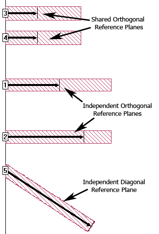
The project editor may change the reference plane slightly so that it is aligned with the edge of a cell. Linked reference planes are indicated by the outline of an arrow while fixed length reference planes are indicated by solid arrows.
To remove a reference plane or calibration length, click on the None radio button and clear the Use fixed calibration length checkbox.
Advanced - Reference plane length sharing: The type and orientation of the reference plane are displayed in the Advanced section of this dialog box. For box wall ports, you may click on the > button to display the settings. When you click on the > button the advanced options are displayed.
Shared reference plane length: Select this option if you wish the reference plane for this port to be the same as other box wall ports on the same box wall. This is the default setting for any new port. When a port is shared, then when the port is de-embedded both the port discontinuity and the coupling between the ports and feedlines are removed.
Independent reference plane length: Select this option if you wish to make the reference plane for this port to be independent. When a port is independent, then the reference plane can be a different length than any or all other reference planes in your circuit. When you choose this setting, the coupling between the independent port and other ports in the circuit is not removed by the de-embedding process; additionally, the coupling between the independent port's feedline and all other feedlines is also not removed.
By default, all reference planes are orthogonal, extending along the x or y plane at right angles to the box wall. When you select this radio button, the "Allow the reference plane to be diagonal" checkbox is enabled. Selecting this checkbox directs the reference plane for the port along the direction of the polygon to which the port is attached rather than at a right angle to the box wall. You should also be aware that, although the S-parameter data is accurate, Z0 and Eeff are not calculated for a diagonal port.
Examples of all reference plane types and orientations are shown below.
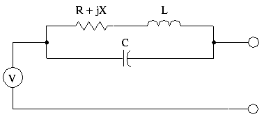
Termination: Enter the four impedance values in the text entry boxes: Resistance (in ohms), Reactance (in ohms), Inductance (in nanohenries), and Capacitance (in picofarads). You may not change the normalizing impedance for Ports numbered zero (0). The entries are disabled whenever the port number is zero.
![]() For a detailed explanation of ports and how they are modeled, please refer to Ports in the Sonnet User's Guide.
For a detailed explanation of ports and how they are modeled, please refer to Ports in the Sonnet User's Guide.