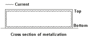
Current Ratio: The current ratio is a parameter used by the Normal metal model, and the Rough metal model when the Cross section is set to “thin”. For these metal models, Sonnet approximates the metal using a single 2D sheet with a thickness of zero. Your real metal, however, has a thickness. At high frequencies, current flows in a thin skin around the edge of the metal. The picture below is a simplified drawing of a conductor with a rectangular cross-section:

Since there are no sides in a zero thickness model; the current which flows on the sides is ignored. The current ratio is defined as the ratio of the current flowing on the top of the metal to the current flowing on the bottom of the metal at very high frequencies, where the thickness is much greater than a skin depth. The current ratio may be set to any non-negative real number.
The default Current Ratio is 0.5. This is a compromise value based on using planar metal in a wide variety of transmission line structures. You can adjust this value as needed for your particular application. To help decide on a suitable value, refer to the table below which gives recommended values for the current ratio for various applications:
Application |
Recommended Current Ratio |
Symmetrical Stripline |
1.0 |
Coplanar Waveguide signal lines |
0.5 |
Microstrip signal lines |
0.5 |
Polygon ground planes below the signal line |
Any large value (e.g., 1000) |
Polygon ground planes above the signal line |
Any small value (e.g. 0.0) |
Analysis box top cover |
See text |
Analysis box bottom cover |
See text |
The table above shows that the current ratio depends on the type of circuit being simulated. For symmetrical stripline, at very high frequency, the current is equally split between the top and bottom surfaces, resulting in a current ratio of 1.0. For microstrip and CPW circuits, the current is usually higher on the bottom side of the metal. The range could be anywhere between 0.0 to 1.0, but in our tests, we have found that the majority of microstrip and CPW traces have a current ratio between 0.4 and 0.6. For ground planes at high frequencies, most of the current flows on the side nearest the signal lines, so you should enter a small current ratio (e.g., 0.0) when the signal line is below the ground plane and enter a large current ratio (e.g., 1000) for when the signal line is above the ground plane.
For the top and bottom covers, em ignores the current ratio of the metal type specified and always uses a small value (0.0) for the top cover and a large value (1e10) for the bottom cover, regardless of the current ratio of the metal type. This is because at high frequency, the current will always flow on the surface of the cover which is nearest the circuit. This was done to allow a single metal type to be used for the circuit metal traces and both covers.