There are six control options for the simplify via array feature which are discussed in detail in the links listed below the graphic. We will use a simple example circuit to illustrate how the options affect the via simplification.
The default values were determined based on extensive testing, and in the majority of cases will provide reasonable via simplification behavior. However, Sonnet handles a wide range of layouts and processes, so these controls were provided so that a user can customize the translation if it proves necessary.
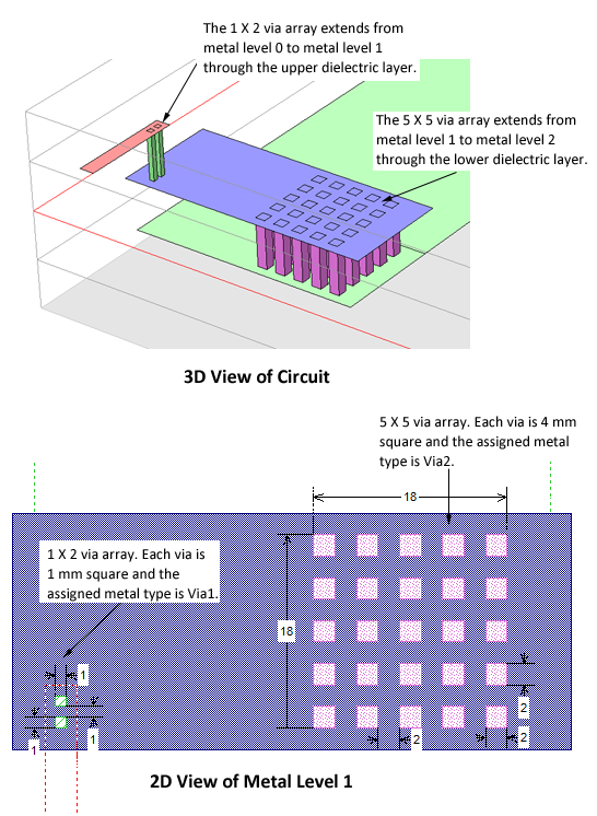
The example structure consists of three metal layers and two interconnecting via arrays, as shown below. Since the vias pass through different dielectric layers and use different metal types, the 1 X 2 array and the 5 X 5 array would never be grouped together. Either reason would be sufficient on its own to prevent these two arrays being grouped together.
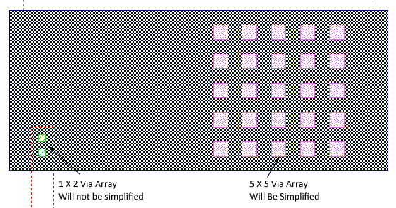
This control defines the minimum number of vias which can be considered part of the same array. The default value for this setting is 5, so that only arrays with 5 or more vias will be considered for simplification. Therefore, in our example the 1 x 2 via array would not be simplified, but the 5 X 5 would be analyzed to see if this array meets the rest of the simplification criteria. You may enter any integer value to set the minimum number required.
This control defines the maximum spacing between vias which can be considered part of the same array. While the distance between vias is measured from the center lines of the individual vias, the control is a ratio of distance to via size. This distance cannot exceed the value of this ratio multiplied by the via size. The default setting is 6.0 and the larger the value, the more widespread the vias can be and still be grouped in the same array. Since individual via cross-sections can be of any shape, the square root of the via area is used as the via size.
For our example the size of the vias is 2.0 mm and the center to center spacing is 4.0 mm, as pictured below. This results in a Distance to Size ratio of 4.0/2.0 = 2.0 so that this array meets the via spacing criteria.
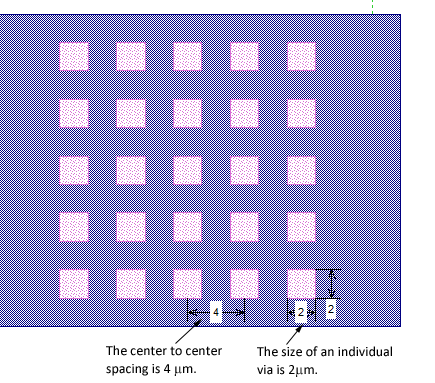
This control defines the maximum allowable difference in via size to be considered part of the same array. The default value of this ratio is 1.5 and the larger the value, the greater the difference of via size is allowed within an array. Since individual via cross-sections can be of any shape, the square root of the via area is used as the via size. For this example, the via cross-section is a 2.0 X 2.0 micron square. The area is 4 μm2 and taking the square root, yields a via size value of 2 microns.
Since all of the vias are the same size in this array (2.0 microns) the Size to Size ratio is 1.0, so that this array meets the via size criteria.
 If you wish to limit your arrays to vias of the same size, set this control to 1.0.
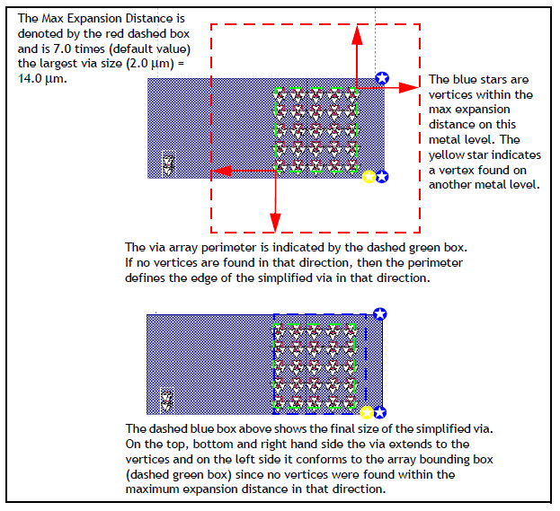
This control helps define the size of the resulting simplified via by allowing it to be larger than the original via array perimeter (also referred to as the bounding box). The default value is 7.0, which allows the simplified via to expand outward by a factor of 7 times the largest via size in the array. The advantage in expanding the simplified via is that it can often be sized to match the polygons to which the via attaches. Having the via polygon edge and pad polygon edge in alignment can significantly reduce the subsection density in the region and thereby reduce the memory requirement of the model.
An example is shown below. The algorithm looks outward from an imaginary rectangle (bounding box) drawn around the perimeter of the array (green rectangle). The distance checked out from the perimeter is the Max Expansion Distance (shown in red arrows). It is equal to the Max Expansion Coefficient times the largest sized existing via in the array. If a vertex from a pad polygon is encountered within this window (red rectangle), the expansion stops and this sets the simplified polygon edge. If no vertices are found in a particular direction, the edge of the simplified via rolls back to the existing via array perimeter. Please note that all metal levels are examined when looking for vertices within the maximum expansion distance.
The default setting for Max Expansion Coefficient is 7.0. If you wish the simplified via to be the bounding box around the array, set the Max Expansion Coefficient to 0, which allows no expansion.
In order to be considered an array, a group of vias must connect to a single polygon on the top and bottom of the group. This control allows the user to merge the polygon pads or traces prior to simplifying the vias. This results in larger arrays being recognized leading to the least number of simplified vias, thereby producing the most efficient model. This option is enabled by default. The option is illustrated below using the example circuit.
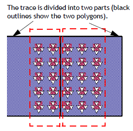
The polygons are only temporarily merged for via simplification and will not be merged in the resulting Sonnet project.