You select Circuit - Subdivide Circuit when you wish to create the geometry subprojects and master netlist for this circuit. You must save any changes in the circuit, including the addition of the subdivision lines, before executing the subdivide command.
The circuit is subdivided where you placed the subdivision lines using Insert - Subdivider. A geometry subproject is created for each section of the circuit and a master netlist connecting all the geometry subprojects is generated.
![]() For a more detailed description of circuit subdivision, see Circuit Subdivision in the Sonnet User's Guide.
For a more detailed description of circuit subdivision, see Circuit Subdivision in the Sonnet User's Guide.
When you select Circuit ⇒ Subdivide Circuit, the Circuit Subdivision dialog box appears, which allows you to input a name for the Main Netlist file which is generated from the subdivide. This netlist connects together the geometry subprojects, generated from each section of the circuit formed by the subdivision lines, in such a way as to model the original circuit.
Circuit Subdivision Dialog Box
Main Netlist Project text entry box: Enter the desired name for the main netlist project generated from the subdivide. You may click on the Browse button to open a browse window which allows you to select a directory on your computer in which you wish to write the netlist. If you select an existing project, you are prompted as to whether you wish to overwrite it, before the command is executed.
Once you have entered a name for the main netlist project and closed the Circuit Subdivision dialog box, the Subproject Specifications dialog box appears which allows you to name the geometry subprojects and optionally add feedlines to the geometry subprojects.
Subproject Specifications Dialog Box
Section Subproject Name text entry box: There is a text entry box for each section of your circuit. Each section corresponds to a generated geometry subproject; enter the desired subproject name for each section. A default name which consists of the main netlist name with the section number appended appears in each text entry box. You may use this name or enter your own.
If you enter an existing project, you are prompted as to whether you wish to overwrite the existing project before the subdivide command is executed.
Length of Feedline with Reference Plane
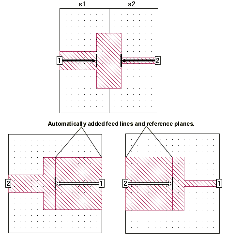
This group of radio buttons in the Subproject Specifications dialog box controls the addition of a feedline with a reference plane attached to any new ports created for the geometry subprojects. Feedlines are not added to ports which were part of your original circuit, but are added to any new ports generated at the subdivision lines, as illustrated below. The added feedlines are grossly exaggerated to demonstrate the process.
Suggested Length radio button: Select this radio button to use the feedline length calculated by the software.
Fixed Length radio button: Select this radio button to enter the desired feedline length you wish to add to the generated ports. Enter the desired feedline length in the adjacent text entry box.
None radio button: Select this button if you do not wish to add any feedline to the generated subprojects.
Once you have entered the desired filenames for the subprojects and selected a setting for the addition of feedlines, you are ready to execute the subdivide.
Subdivide button: Click on this button to execute the subdivide command. The geometry subprojects and the master netlist are generated. The master netlist is opened in the project editor.