There are five models available: Touchstone S-Parameters, Spectre S-Parameters, Broadband Spice, N-Coupled Line and Inductor. The five types of models are handled in a very similar manner so that the ensuing discussion applies to all types of models.
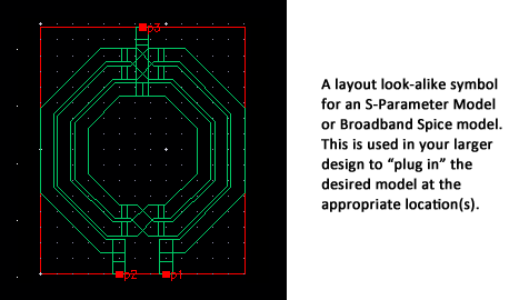
When you specify any model, a schematic view of the model and a symbol for the model are created. The symbol can be a layout look-alike (default) or a black box. To view the model, select Models ⇒ <Model Type> ⇒ Show View to open a view of the schematic, the symbol and the View <Model Type> Model dialog box. An example is shown below. The “Add Ref. Pin” option was selected in the Model Symbol Options dialog box, so that a reference pin appears in the schematic.
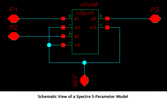
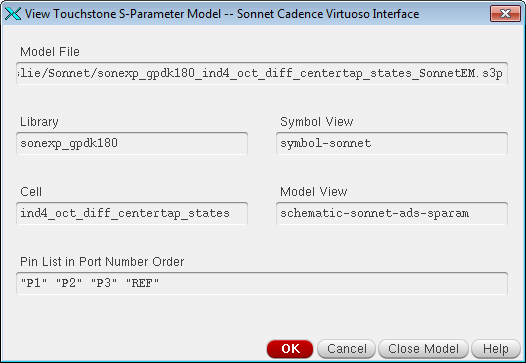
The View Model dialog box, which appears when you view the model, provides information about the model including the name of the symbol view and the model view.
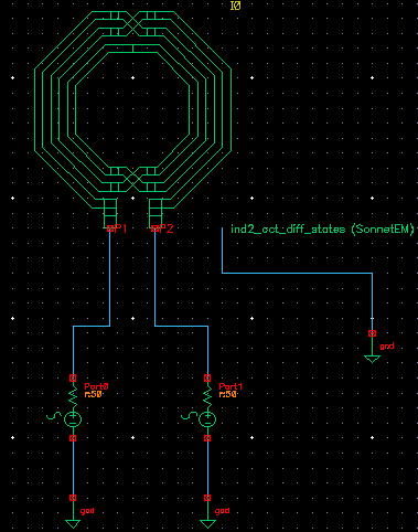
For all models, the Symbol view is automatically created along with the model. You use the symbol view in your schematic design. You plug in the symbol created by the Cadence Virtuoso Interface so that the S-parameter model or Broadband Spice model will be used in the Cadence simulation.
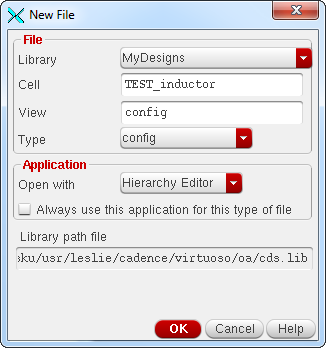
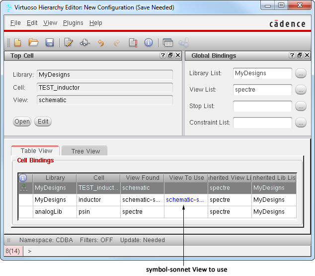
In order to use a model in the Analog Design Environment, it is recommended that you create a config view which references the Sonnet symbol. This is because when you create multiple models from an analysis, only one symbol is created and shared among all of the models. The configuration view allows you to easily switch which model the symbol is representing. To set up the environment to use your model, do the following:
The Choosing Design dialog box appears on your display. 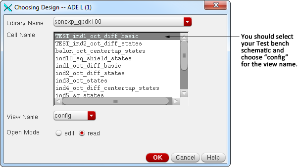
When you choose the Test bench Cell name, the View Name should be set to config, as shown above. When you close the dialog box, the title bar of the Analog Design Environment window is updated with the Cell you have chosen.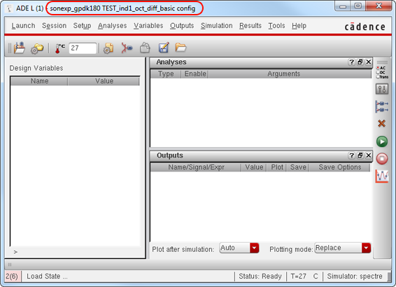
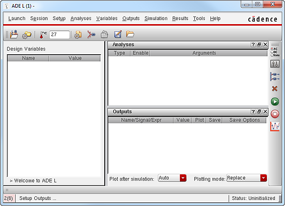
The model is loaded and ready to use in your simulation.