The Component is represented in your circuit by a component symbol. The label of the Component appears above the component symbol and the terminal numbers are identified there. Ports, indicating where the terminals of the Component are connected to the metal in your circuit, are represented by a small rectangle. Component ports are only numbered when the Component model type is Ports Only. An example of a Component as it appears in the project editor is shown below.
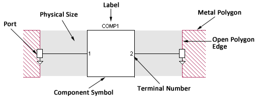
Component Symbol: This is the symbol which represents your Component in your project.
Port: The Component port defines the point at which the Component is connected to the circuit metal and must be attached to an open polygon edge. This point also serves as a reference plane for de-embedding the Component unless a reference plane is added for the port. There is one Component port for each terminal on the Component. Component ports are modeled using co-calibrated internal ports. For more information on co-calibrated ports, please see Co-calibrated Internal Ports. If the component type is a Sonnet project, the terminals correspond to the ports in the Sonnet project.
Terminal Numbers: Terminal numbers identify the physical pin on your Component connected to the corresponding Component port.
Components may have an unlimited number of terminals, with the exception of those Components which use the Ideal Component model, since the available ideal components are limited to two terminals. Terminals and/or ports are numbered in the order in which they are added to your circuit and may be modified after the Component is added to your circuit.
Label: The label is user-defined text which identifies the Component in your circuit. Each Component label in a project must be unique.
Open Polygon Edge: Component ports may be placed only on open polygon edges. You may use a reference plane to control how much, if any, of your circuit metal is also de-embedded in addition to the Component. For more information, see Shifting Reference Planes.
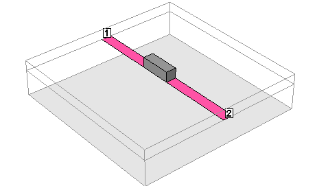
Physical Size: You may also optionally enter a physical package size for your Component. These measurements (height, width, and length) are not used in the em simulation but are there to provide a graphic in both the 2D and 3D view which represent the actual size of the Component. This is especially useful for design presentations and reviews. Shown below is a 3D view of the example Component pictured above: