In order to apply the diagonal feature to a port, you must first add the port to the circuit. A new port defaults to being an orthogonal port. After the port has been added, you may use the Port Properties dialog box to select the diagonal feature and specify the reference planes. Detailed instructions are provided below.
- Add the desired ports to your circuit.
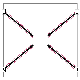
For instructions on adding a port, please see Adding Ports in Sonnet's Project Editor. An example circuit with four box-wall ports is shown below.
- Double click on a port to open the Port Properties dialog box.
You can also select a port and then use the Object ⇒ Port Properties command in the project editor’s main menu to open this dialog box.
- Click on the arrow labeled Advanced - Reference plane length sharing.
This appearance of the dialog box is updated and the reference plane length sharing options are displayed.
- Click on the “Independent reference plane length” radio button.
This option is used to make the reference plane for this port independent of other reference planes for other ports. By default all ports on the same box-wall (or same side for components or co-calibrated port groups) share the same reference plane length. This feature allows you to use a different reference plane length for this port, regardless of reference plane lengths for other ports, even ports which share a box-wall. A port cannot use the diagonal feature unless it is using an independent reference plane. When you select this option, the “Allow the reference plane to be diagonal” checkbox is enabled.
- Select the Allow the reference plane to be diagonal checkbox to enable it.
This option allows your reference plane to extend at any angle in your circuit, instead of limiting it to be orthogonal. The polygon to which the port is attached is used to determine the direction of the reference plane instead of the box-wall.
- Select Fixed or Linked from the reference plane type drop list.
This determines if you enter a length or link to a point on a polygon to set the length.
- Click on the Use Mouse button to set the reference plane length for the port.
Clicking on the Use Mouse button allows you to click in your circuit to define the reference plane or if you defined the reference plane as linked, to select a point of a polygon. When you click on the icon, the dialog box disappears from your display so that you may access the window.
- Click at the desired location for the reference plane.
For this example, the reference plane is set at the end of the polygon to which the port is attached so that the transmission line effects for the whole feedline are removed during de-embedding. After clicking at the end of the polygon, the Port Properties dialog box reappears with a length entered in the Ref. Plane text entry box. Note that for a fixed reference plane you could just have entered a length into this text entry box.
- Click on the OK button to close the dialog box and apply the changes.
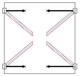
The reference plane is drawn, along the polygon, as shown for all four of the ports below. This completes applying the diagonal feature to your port. To complete this design, you would follow the same procedure for the other three ports.