When you create a metal type in your project, you can use your own custom metal by manually entering the loss parameters or you can use a metal type from the metal library. To define a new planar metal type by manually entering the loss parameters, do the following:
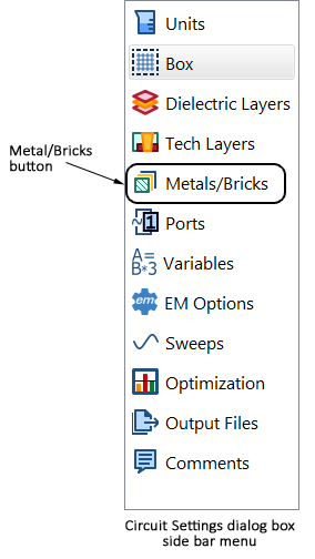
The Circuit Settings dialog box appears.
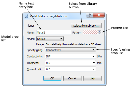
The Metal Editor dialog box appears on your display.
This dialog box is also opened when you click on the New or Edit button in the Technology Layer Editor when editing a Metal Technology Layer.
A default name appears in the Name text entry box. If you wish to change the name, edit the Name text entry box.
The input fields for the metal properties are updated to reflect the Model you select. When you select a model type, the appearance of the dialog box is updated with the input parameters for that model type.
The dialog box is updated to display a text entry box for whichever parameter you choose.
For more details about how the parameters are used, see Planar Metal Editor dialog box.
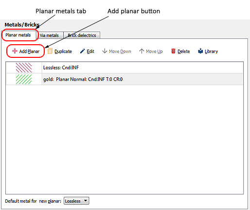
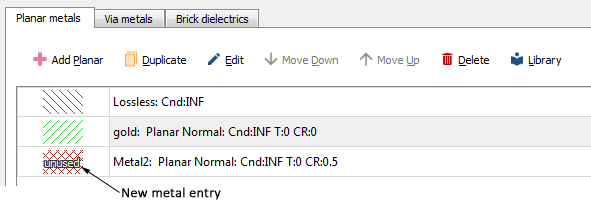
This metal now appears in the metal list in the Planar metals tab. The entry is displayed with "unused" on top of the pattern since this metal type is presently not assigned to any metal in your circuit. You may also select this metal as your Default metal for new planar.
This metal type is now available to apply to polygons and the top and bottom metal of the Sonnet box.