Anchored and symmetric parameters have a setting which controls how the adjustable point sets are moved. There are three settings: Move points the same distance, Scale points in one direction, and Scale points in X and Y. Each type is explained below.
Below is shown the Parameter Properties dialog box in which you select the moving option from the drop list. This dialog box appears when you are entering a dimension parameter or when you select the command Object ⇒ Parameter Properties when a dimension parameter is selected.
This setting moves the adjustable point set the same distance as the reference point is moved and all the points in the adjustable point set maintain their relative position. This is the default setting. An example using an anchored dimension parameter is shown below. Note that the adjustable point sets are highlighted.
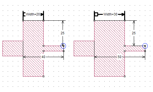
The anchored dimension parameter is increased by 10 mils, so each point in the adjustable point set is moved away from the anchor point by 10 mils. As shown in the illustration, the original distance from the anchor to the circled point was 40 mils; when the value of the parameter is increased, the point was moved by 10 mils so that it is now 50 mils away from the anchor point.
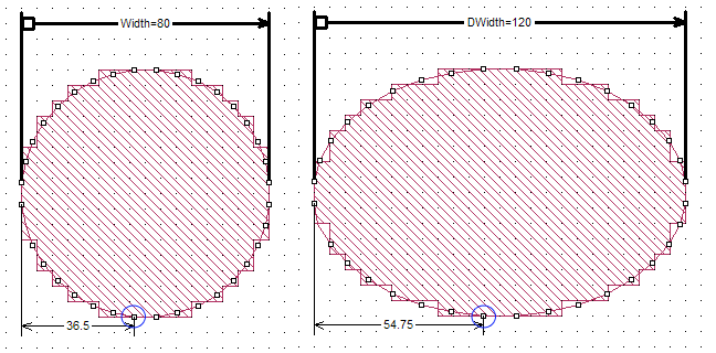
When using this setting, the geometry controlled by the parameter is scaled or stretched along either the x or y axis depending on the orientation of the parameter. Each point in the adjustable point set is moved by an amount based on its relative distance from the anchor. Points closer to the anchor are moved a smaller distance then points further away from the anchor. For symmetric parameters, the anchor is the center point between the two reference points.
The scaling factor used is the ratio of the new nominal value to the present nominal value. Each point is moved by a delta calculated by multiplying its present distance from the anchor point by the scaling factor.
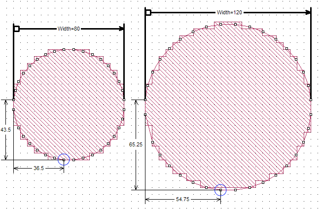
When using this setting, the geometry controlled by the parameter is scaled or stretched along both the x and y axis keeping the proportions of the geometry the same. Each point in the adjustable point set is moved by an amount based on its relative distance from the anchor. Points closer to the anchor are moved a smaller distance then points further away from the anchor. For symmetric parameters, the anchor is the center point between the two reference points.
The scaling factor used is the ratio of the new nominal value to the present nominal value. Each point is moved by a delta calculated by multiplying its present distance from the anchor point by the scaling factor.
An anchored dimension parameter being scaled in both directions is shown below. The scaling factor is 1.5 since the new nominal value is 120 mils and the present value is 80 mils. As shown in the illustration, the original distance from the anchor of the circled point was 36.5 mils along the x axis and 43.5 mils along the y axis; when the value of the parameter is increased the point was moved to 54.75 mils away from the anchor point along the x axis and 65.25 mils along the y axis; the original distances multiplied by the scaling factor of 1.5.