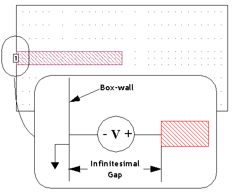
A standard Box-wall port is a grounded port, with one terminal attached to a polygon edge coincident with a Box-wall and the second terminal attached to the Box-wall. The port, therefore, breaks the connection between the polygon and the wall and is inserted in an “infinitesimal” gap between the polygon and the wall. The signal (plus) portion of the port goes to the polygon, while the ground (negative) portion of the port is attached to the Box-wall (ground). An example of a standard Box-wall port is shown below. Standard Box-wall ports can be de-embedded and can also have reference planes. This type of port is the most commonly used.
Reference planes and calibration lengths are both used during the de-embedding process in which the analysis engine, em removes the port discontinuity and a desired length of transmission line. For details of how these values are used during the de-embedding process, please refer to De-embedding.
For a Box-wall port, you may set either a reference plane or a calibration length; both values cannot be set at the same time for Box-wall ports because when a reference plane is set, the calibration length must equal the reference plane length. Ports can be shared, in which case all shared ports on the same Box-wall use the same reference plane length or calibration standard length. If the port is set to independent, then a reference plane or calibration standard may be set that applies only to that port. Please note that if the port is independent, then the coupling between ports is not de-embedded; coupling is only removed between shared ports. To set either of these values for Box-wall ports, use the Object ⇒ Port Properties command.