For some applications, it is necessary to account for the physical thickness of a planar conductor when computing the coupling between that conductor and other nearby conductors. Examples of such applications include:
• Spiral inductors where the thickness of each turn is comparable to, or greater than, the gap between the turns.
• Interdigital capacitors where the side-to-side capacitance between fingers is fundamental to the performance of the capacitor.
• Transmission lines which cross over one another when the line thicknesses are on the same order or larger than the gap thickness between the lines.
Sonnet provides three separate planar models for which physical thickness is applied as the conductors are meshed an coupling computed. These planar metal models are as follows:
• Thick Metal Model
• Rough Metal
• TrueVolume
These three models are described in detail below.
The Thick Metal Model approximates a thick conductor by modeling that conductor with two or more infinitely thin sheets of metal electrically connected along the edges with vias. The number of sheets used by the model is an input parameter. The default number of sheets is two, with the upper sheet placed at the top surface of the conductor, and the lower sheet placed at the bottom surface of the conductor. A 3D illustration of how a thick conductor is meshed when the Thick Metal Model is used with two sheets is shown below:
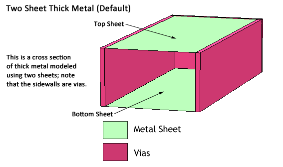
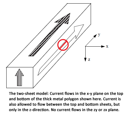
It is important to note that the via walls along the edges of the conductor carry only z-directed current. XY-directed current will only flow in the infinitely thin planar sheets. For the two sheet Thick Metal Model, this means that the XY-directed current only flows on the upper and lower surfaces of the conductor.
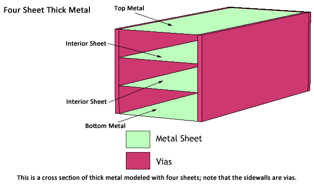
For most cases, using the default of the two sheets provides a sufficiently accurate solution. However, for tightly coupled lines, where the gap between the lines is less than the metal thickness, coupling between the lines may be underestimated if only 2 sheets are used. Under this circumstance, increasing the number of sheets used will improve the accuracy of the coupling calculations. Please note, however that increasing the number of sheets used will also result in higher memory requirements and longer processing time for the simulation. A 3D illustration of a how a metal thick conductor is meshed when the Thick Metal Model is used with four sheets is shown below:
The Rough Metal Model allows the effects of surface roughness to be included in the simulation. This model supports both physically thin and physically thick metal. In the case of physically thick metal, the Rough metal model is physically equivalent to the Thick Metal Model with two sheets. That is, the physically thick Rough Metal model consists of two infinitely thin sheets of planar metal electrically connected along the edges with vias. The only difference between the two models is that surface impedance calculations for the Rough Metal model include the effects of surface roughness, whereas the two-sheet Thick Metal Model assumes that the upper and lower metal surfaces are smooth.
The TrueVolume model divides the volume of a thick conductor into rectangular metal cubes, and then uses Sonnet's volume subsections to model those cubes. These volume subsections account for the full 3D geometry of a subsection in all coupling calculations. Therefore, the physical thickness of the metal conductor is inherently accounted for with the use of volume subsections.
The vertical divisions or Z-meshing of the thick conductor, are optimized to automatically provide maximum accuracy in terms of metallization loss and capacity coupling. This is important as the distribution of current on and within a thick conductor is a function of the metal properties, frequency, and the proximity of the conductor to other nearby conductors. Sonnet provides two options to control this Z-mesh method:
• Single layer surface
• Double layer surface
The Single layer surface method is the default method, and it has the minimum requirements in terms of memory usages and simulation time. Shown below is a cross-section of a TrueVolume conductor using the Single layer surface Z-mesh method:
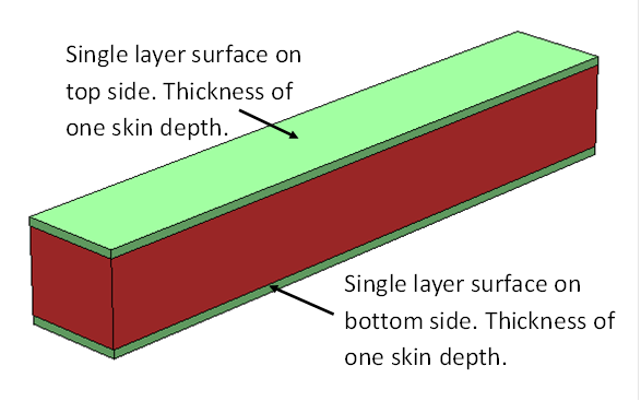
For this method , the TrueVolume conductor is divided into three layers:
1) One skin depth thick surface layer on the top side.
2) Middle Layer
3) One skin depth thick surface layer on the bottom side.
The Double layer surface method is the preferred method when there is strong capacitive coupling between the TrueVolume conductor and other nearby conductors. Shown below is a cross-section of a TrueVolume conductor using the Double layer surface Z-mesh method:
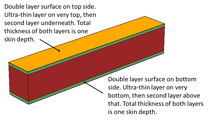
For this method, the True Volume conductor is divided into five layers:
1) Ultra-thin outer layer on the top side. Required for accurate capacitive coupling calculations.
2) Internal layer near the top side. Sum of layers 1) and 2) is one skin depth thick
3) Middle layer.
4) Internal layer near bottom side. Sum of layers 4) and 5) is one skin depth thick.
5) Ultra-thin out layer on bottom side. Required for accurate capacitive coupling calculations.