Calibration Standards
In order to properly de-embed the ports of a project, Sonnet electromagnetically analyzes several calibration standards which include the same port discontinuities that are in the primary circuit. This process is automatic and you rarely need to worry about it. However, there are some specific applications where understanding calibration standards may be required in order to obtain accurate results in a reasonable amount of time.
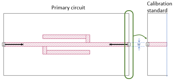
An example primary circuit is shown below, along with a Box-wall Port calibration standard to the right. The green oval indicates the region considered when the Port 1 calibration standard is constructed. Notice that it consists of a transmission line with the same width as the line connected to Port 1 in the primary circuit. Notice also that the length of line in the calibration standard is equal to the length of the reference plane.
Box-wall ports
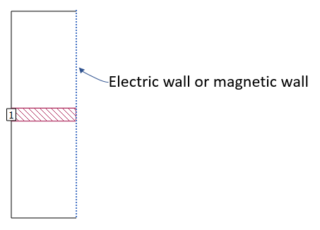
For Box-wall ports, Sonnet uses the Short Open Calibration (SOC) technique which means a short and open transmission line standard must be analyzed. For a single port on the box wall, the two calibration standards look like the picture below, where the dashed line is replaced with an electric wall (for the short circuit) and a magnetic wall (for the open circuit).
The picture above represents the simplest case. A few of the more complex cases are discussed below.
Coupled Lines
When two or more Box-wall ports are on the same box wall, the calibration standards are composed of coupled transmission lines. In the example below, primary circuit Ports 2 through 6 are on the right box wall, so five transmission lines are required in the calibration standard. The calibration standard ports are renumbered and the metal properties are the same as those used in the primary circuit.

A CPW Example
For a Box-wall port, the calibration standard is based on all polygons that touch the same box wall. In the CPW example below, the calibration standard for Port 1 includes a signal line, ground metal on two levels, and two ground vias because they all touch the box wall. The calibration standard for Port 2 includes the signal line and ground metal, but does not contain the ground vias as they do not touch the box wall. In both calibration standards, the geometry at the box wall is extended to the specified calibration standard length.

The calibration standard for Port 2 can support multiple modes of propagation because the ground metal polygons are not connected together with vias. Since de-embedding requires one mode of propagation per port, the de-embedded results could be inaccurate. Often this shows up as a resonance in the results. To avoid these errors, either place vias on the box wall manually, or specify an electrically short calibration standard length (see Calibration Standard Length).
Co-calibrated Ports
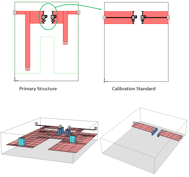
For Co-calibrated ports, the calibration standard is based on all the ports in a calibration group. In the example below, Co-calibrated Ports 3 and 4 are in close proximity, so they will be in the same calibration group.
With this calibration standard construction, all coupling between Port 3 and Port 4 will be negated during de-embedding. In the 3D subsection view, the darker blue via subsections are the Generalized Local Ground (GLG) metal used to establish the bottom box cover as the port ground reference.

In the example below, Port 3 and Port 4 are Co-calibrated ports that use a floating ground reference. The terminal width of the ports is set smaller than the trace width to which the ports connect. The calibration standard width corresponds to the narrower terminal width value.
In the 3D subsection view, the darker blue planar metal subsections are the Generalized Local Ground (GLG) metal used to establish a ground reference for the ports.

In the example below, Port 3 and Port 4 are Co-calibrated ports that use the lower polygon plane as a ground reference.
In the 3D subsection view, the blue via subsections are the Generalized Local Ground (GLG) metal used to establish the bottom box cover as the port ground reference. Note the calibration standard for polygon plane uses the bottom box cover in place of the polygon plane.
Calibration Standard Length
By default, the calibration standard length is automatically determined during the analysis. Sometimes the automatic length is longer than necessary, but in most cases the extra analysis time is negligible. Extra calibration standard length can add a significant amount of analysis time in circuits where there is a lot of metal such as CPW, or in circuits with very long feedlines.
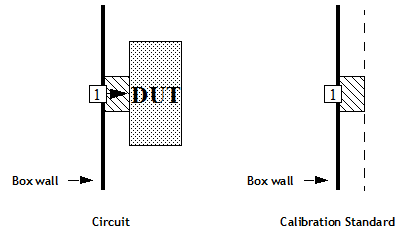
There are also cases where the automatically determined calibration standard length is too short. This can cause errors in the de-embedded results due to the lack of an established TEM or quasi-TEM mode. A Box-wall port with a calibration standard which is too short is illustrated below. Notice the length of the calibration standard is even shorter than the width of the line.
 In these cases, you may wish to override the automatically determined length. The table below shows for which port types you may set the calibration length manually.
|
Port Type |
Default Cal Length |
Manual Setting of Cal Length? |
|
Box-wall with reference plane |
Reference plane length |
No (see text below) |
|
Box-wall without reference plane |
Automatic |
Yes |
|
Co-calibrated |
Automatic |
Yes |
|
Delta Gap |
Automatic |
No |
The second column shows how the default calibration length is determined. The third column shows whether a manual setting is possible. For Box-wall ports which have a reference plane, changing the reference plane length changes the calibration standard length. For ports which allow you to change the calibration length, double-click the port and enter the desired value in the Use fixed calibration length text entry box.