Pi Model
The Pi Model may be used for circuits that are electrically small (typically less than 1/20 of a wavelength) and can be represented by a simple pi topology. The results are usually valid only over a narrow frequency band. These limitations are due to the circuit theory limitations of modeling a circuit with just a few lumped elements. The Sonnet electromagnetic analysis is not intrinsically limited in this fashion.
Creating the Model File
You must simulate at two or more frequencies to obtain a Pi Model. There are two methods you may use to generate a Pi Model file:
Automatic: You may set up your project so the EM solver will automatically generate a Pi Model file. From the Project Editor, select Circuit > Settings > [Output Files] and then select Add File > Pi Model.
Interactive: After simulating your project, you may generate the file from a Sonnet graph. Select a curve representing the desired project, and then select Output > Pi Model File.
Topology Used for Pi Model Output
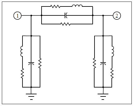
The topology of the lumped element model generated by the EM solver depends on the circuit being analyzed. For the most general case, the model contains a series RL and a parallel RC connected from each port to ground. A similar parallel network is also connected between each port. In addition, each inductor may also have a mutual inductance to any other inductor in the network. The figure below shows the most complex equivalent circuit possible for a two-port (mutual inductances not shown).
The synthesis capability does not allow internal nodes (nodes which are not connected to a port in the layout) with the single exception of the internal node required for the series RL. Any circuit which requires internal nodes for an accurate model should be split into several projects.
Model Options
You may obtain a short description for each option by hovering your mouse over the option in any dialog box. See the descriptions below for those options which require additional information.
Frequency Separation
The Pi Model synthesis needs data at two or more frequencies. A Pi Model is created for pairs of frequencies. The second frequency is determined by taking the first frequency and adding a percentage specified in the Separation field (default is 10%). The second frequency then becomes the first frequency for the next pair of frequencies for which a Pi Model is generated. The synthesis continues in this way until all the frequencies have been used.
Threshold Values
By default, if an element value has a high impedance, it is excluded from the model. This helps simplify the model but may leave out an element that you need. You may control the threshold required for the element to be excluded using the following options:
RMAX: Maximum allowed resistance (ohms). The default value is 1000.0 ohms.
CMIN: Minimum allowed capacitance (pF). The default value is 0.01 pF.
LMAX: Maximum allowed inductance (nH). The default value is 100.0 nH.
KMIN: Minimum allowed mutual inductance (dimensionless ratio). The default value is 0.01.
RZERO: Resistor to go in series with all lossless resistors (ohms). Needed for some versions of SPICE which need resistors to have some small loss to avoid numerical difficulties. The default value is 0.0, which disables this capability.