Snap/Ortho
Select View > Options > [Snap/Ortho] to control how your cursor movement is constrained. These settings affect how objects are created and moved, including placement of vertices and the placement of polygons when moving them. See the appropriate section below for a more detailed explanation.
Grid Snap
By default, your cursor is constrained in increments of a cell.
The grid snap setting does not affect the size or location of your subsections. Subsections are always based on the cell grid, regardless of the snap settings.
The snap options are as follows:
On: If you unselect this checkbox, grid snap is turned off. The cursor is not confined to the snap grid. Instead, the movement is constrained to the nearest pixel.
X and Y: Selecting this radio button causes the Grid Snap settings to apply to both the x and y direction.
X Only: Selecting this radio button causes the Grid Snap settings to apply to the x-direction only. Grid snap is disabled for the y-direction.
Y Only: Selecting this radio button causes the Grid Snap settings to apply to the y-direction only. Grid snap is disabled for the x-direction.
You select one of the following radio buttons to select your grid snap type:
Cell Size: Constrains your cursor to increments of a single cell. The present cell size is displayed to the right of the radio button. This is the default setting.
Divide Cell: Sets the snap to match a subdivision of a cell. Enter the number of divisions per cell.
Custom: Any arbitrary snap grid can be specified by entering the desired values in the X and Y text boxes. Use this option if, for example, you want to create or move a polygon with all coordinates snapped to the nearest micron.
You may quickly turn snap on or off by selecting Edit > Snap or toggling the Snap toolbar button:  .
.
Snap Polygon Points
You may snap the points of one or more selected polygons or complete polygons to the grid. To do so, select Object > Snap To. This opens the Snap Objects dialog box as shown below: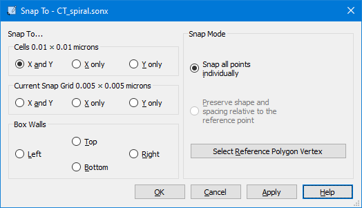
Snap To Section
Cells: All points on the selected polygons are aligned to the grid. You can choose to snap points in both the X and Y direction, only the X direction, or only the Y direction.
Current Snap Grid: All selected points are snapped to the Snap Grid as defined in the Snap/Ortho pane of the View Options dialog box. If the current Snap Grid is set to the cell size, then this option is not enabled, since in that case, the Cells option above is the equivalent of this selection. You can choose to align points in both the X and Y direction, only the X direction, or only the Y direction.
Box Walls: This option is enabled only if you are in edit points mode and have selected points on a polygon. You then select an Analysis Box wall: Left, Right, Top or Bottom. All selected points will be moved to the corresponding wall.
Snap Mode Section
When you snap a circuit to the grid, you have a choice of snapping each vertex on all the polygon(s) to the grid or selecting a reference point to snap and having all other vertices maintain their position relative to that reference point.
Snap all points individually: Select this radio button to snap all the vertices in the selected polygons to the grid when you perform the snap command.
Preserve shape and spacing relative to the reference point: Select this radio button if you wish to snap a reference point contained in the selected polygon(s) to the grid with all other vertices maintaining their position relative to the reference point. For example, if a vertex is 3 mm below the reference point, it will still be 3 mm below the reference point after the snap is completed. This option is disabled until you click the Select Reference Point button.
Select Reference Point: Click this button to select the reference point to be used during the snap command. This reference point is used for the Preserve shape and spacing option. When you click on the button, a ''+'' cursor appears on your display. Click the desired reference point.
The points are not snapped until you click the OK or Apply buttons.
Ortho
Ortho mode constrains the creation and movement of points and polygons to specific angles. Select Edit > Ortho to place the Project Editor in Ortho mode. This will affect you in two ways:
- First, if you add a polygon while Ortho mode is active, the Project Editor will only allow horizontal, vertical or multiples of the angle in the Ortho Angles drop-down list.
- Second, when moving a selected object or point, the movement is limited to multiples of the angle selected in the Ortho Angles drop-down list. For example, if 45 degrees is selected, then an object may be moved in the horizontal plane (0 degrees), in the vertical plane (90 degrees) and along an axis of 45 degrees. Available angles are 90, 45, 30, 22.5, and 5. The default is 45.
Holding down the Shift key while adding, moving, or editing objects will temporarily place you in Ortho mode. In addition, you may toggle Ortho mode by selecting Edit > Ortho or toggling the Ortho toolbar button:  .
.