A co-calibrated port is always associated with a calibration group. A calibration group uses a common ground node connection. When em performs the electromagnetic analysis, the co-calibrated ports within a group are simultaneously de-embedded using a high accuracy de-embedding technique; thus, coupling between all the ports within a calibration group is removed during de-embedding.
Co-calibrated internal ports are automatically added to a calibration group made up of ports in reasonable proximity who also share the same type of ground reference. If you change the ground reference of a co-calibrated port, such that it is different from the ground references of the other ports in a calibration group, that port is no longer included in that group by the software. If you wish to observe the grouping determined by the software before running your analysis, you may select the command View - View Subsections from the project editor main menu.
It is also possible to manually define a calibration group which overrides the automatic settings. For more information, please refer to Create a Calibration Group Manually.
For a detailed explanation of the rules used in grouping co-calibrated ports, please see Rules for Co-Calibrated Ports.
You must define how the common ground of your calibration group is connected to your circuit. There are four choices for ground reference: Auto, Box Cover, Polygon Plane and Floating. The port symbol used in the project editor indicates the type of ground reference as shown in the table below. If you are using a Sonnet Technology File with encrypted proprietary information, the ground reference for a co-calibrated port is Hidden.
Symbol |
Ground Reference |
|
Box Top |
|
Box Bottom |
|
Polygon Plane Above |
|
Polygon Plane Below |
|
Floating |
|
Hidden |
Auto: When the ground reference is Auto, the software determines where to place the ground reference. The type of ground reference used is indicated by the port symbol.
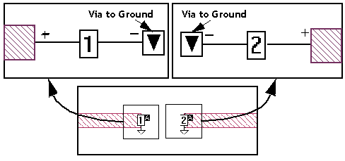
Box Cover: When the ground reference is defined as the Box Cover, all co-calibrated ports in the group are globally grounded to a box cover. To do this, a via is automatically created which connects to the top or bottom cover of the analysis box. You should choose this option if the element model or measured data to be connected to these ports includes shunt elements. Examples are:
This type of co-calibrated port is illustrated below. The positive terminal is attached to a polygon edge of a feedline and the negative terminal is attached to a via to ground which is removed during de-embedding.
When the Box Cover is selected as the ground reference, you also select a ground direction. If the ground direction is set to Auto Direction, the software automatically determines the most efficient direction the ground via should extend taking into consideration the distance, the electrical properties of the dielectric layers between the port and the box covers, and the loss of the box top or bottom box cover. The selected direction is shown in the port symbol as illustrated in the table above. You may also select the top cover by selecting Above, or the box bottom by selecting Below. When using this type of ground, you must make sure that there is a clear path with no metal on other levels interfering with the path to the box top or bottom.
In addition, either the box top or bottom must have loss less than 50 ohms/sq. For example, you should not use “Free Space” for both your box top and bottom definition. If the loss is too high on both the box top and bottom for a ground via from the calibration group to be attached, the analysis engine will issue an error message.
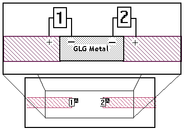
Floating: When the ground reference is defined as Floating, all co-calibrated ports in the group are connected to a common ground but not to the analysis box. Instead, the ground reference is left unconnected to the rest of your circuit. You should choose this option if the element model or measurement data that will be connected to these ports does not have a ground reference, or does not have shunt elements. Examples of this are:
This type of co-calibrated port is illustrated below. Sonnet automatically adds extra metal which connects the co-calibrated ports in a calibration group. This extra metal is defined as Generalized Local Ground (GLG) metal since it acts as a local ground for the ports in the calibration group. This metal is removed during the de-embedding process. The positive terminal of a co-calibrated port is attached to a polygon edge of a feedline and the negative terminal is attached to GLG metal.
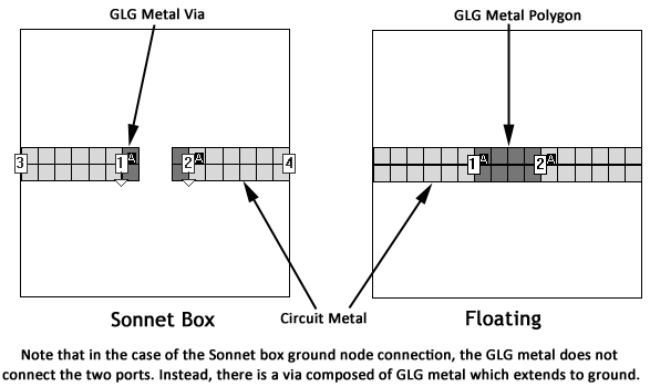
To observe the GLG metal for either type of ground node connection, you may select the View - View Subsections command in the project editor. When the Subsection Viewer appears, select View - GLG Metal from the subsection viewer’s main menu. Views of two calibration groups, as viewed in the subsection viewer with the GLG metal displayed, are shown below. A calibration group which is grounded to the analysis box is shown on the left and one with a floating ground is shown on the right.
Polygon Plane: When the ground reference is defined as Polygon Plane, all co-calibrated ports in the group are connected to a polygon above the present level, below the present level or both above and below the present level. The ground for the co-calibrated port is attached to the first polygon encountered in the direction specified for the ground reference. When using this type of ground, you must make sure that there is a clear path with no metal on other levels interfering with the path to desired ground plane polygon.
In addition, the polygon used as the ground reference must have loss less than 50 ohms/sq. If the loss is too high, the analysis engine will issue an error message. The polygon should also be large enough to be used as a ground plane. The metal polygon used as a ground reference is modeled as an infinite plane when the de-embedding is done by the analysis engine.
This type of ground reference is illustrated below.
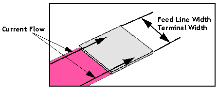
You must also determine how you will define the terminal width for your calibration group. Terminal width is the electrical contact width of the component which is to be attached. This allows the current flow from the circuit geometry into the component to be accurately modeled. There are three settings for terminal width: Feedline Width, One Cell, and Custom. The terminal width is indicated by a  symbol in the project editor.
Feedline Width: This defines the terminal width as equal to the the width of the feedline to which the co-calibrated port is attached. This is illustrated below.
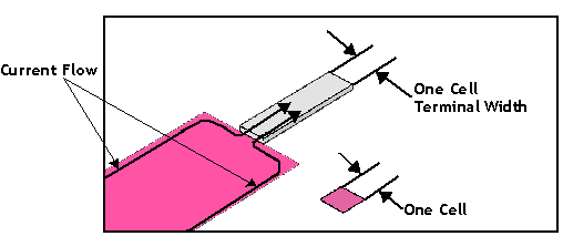
One Cell: This defines the terminal width to the smallest possible size as pictured below.
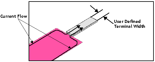
Custom: This allows you to enter any value desired for the terminal width. This type of Terminal Width is shown below.
The terminal width is indicated in the project editor view by a black line with a "T" at either end as pictured below for all three option of terminal width.