The set of criteria used by the software when autogrouping co-calibrated ports is as follows:
The physical layout rules are detailed in this section. Note that these rules should also be followed when manually defining a calibration group. For detailed instructions on manually creating a calibration group, please refer to Create a Calibration Group Manually.
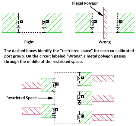
- No objects may be placed within the “restricted space” in the interior of the co-calibrated port group
Metal polygons, vias, or dielectric bricks may not be present in the rectangular area defined by the port locations and the terminal widths, as illustrated below. The bottom circuit shows the restricted area in a calibration group. For the best possible accuracy, no objects should be present in the restricted space, even on layers above or below the port layer.
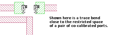
- Nearby objects should be placed so that coupling between the co-calibrated ports and the object does not occur:
Co-calibrated ports should be placed such that coupling is minimized to circuit traces and vias, as shown below.
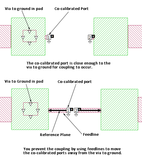
It can be helpful to add feedlines to all co-calibrated ports, then use reference planes to remove the effect of the feedlines. This allows you to place the ports and any ground reference vias far enough away from other circuit elements to prevent coupling. Note that in order to use reference planes for a co-calibrated port, your ground reference cannot be set to "Floating."
In the illustration below, the top circuit places the co-calibrated port close enough to the via to ground in the pad for coupling to occur. In the bottom circuit, feedlines have been added to move the co-calibrated ports further away in order to prevent any coupling to the via. Reference planes are set for the co-calibrated ports to remove the effects of the feedlines during the de-embedding process.
In circuits with a large number of co-calibrated ports, it may be useful to place the co-calibrated ports with only a one cell gap between them. This decreases the chance of coupling with other circuit elements even further. Full accuracy is maintained even at a one cell distance. This also has the added advantage of forcing a single ground reference via (when using the Sonnet box or a planar polygon as the ground reference) which removes unnecessary via subsections and reduces the memory requirements for your analysis.
- Co-calibrated ports whose ground references are defined as the box cover require direct access to a low loss top or bottom cover:
When using this type of ground, you must make sure that there is a clear path with no metal on other levels interfering with the path to either the box top or box bottom.
In addition, the box cover used as a ground reference should not have loss greater than 50 ohms/sq. If the loss is too high on both the box top and bottom, the analysis engine issues an error message.
- Co-calibrated ports whose ground references are defined as Polygon Plane require direct access to the polygon used as the ground reference.
When using this type of ground, you must make sure that there is a clear path with no metal on other levels interfering with the path to the ground reference polygon. In addition, the polygon should not have loss greater than 50 ohms/sq. If the loss is too high, the analysis engine issues an error message.
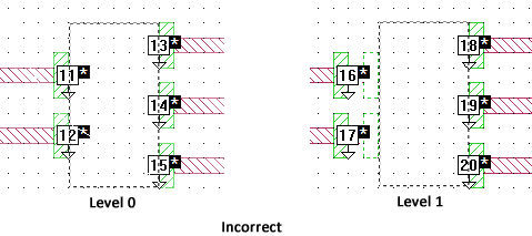
- Multiple ports on the same side of the restricted area should be aligned:
In the illustration below, the co-calibrated ports on the left are placed incorrectly and will produce an error during an analysis. The ports on the right are placed correctly.
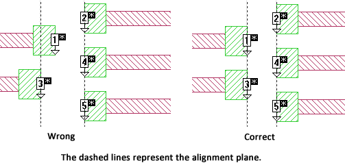
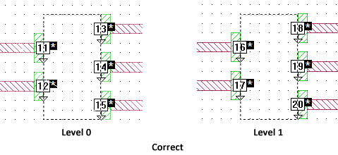
For multi-level co-calibrated ports, ports on different metal levels need to be aligned in the x, y plane. In the illustrations below, the multi-level calibration group on top is correct. The one on the bottom is incorrect since the ports on the left side of metal level 0 are not aligned with the ports on the left side of metal level 1
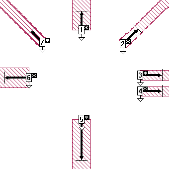
- Reference planes for each side of a co-calibrated port group are shared and therefore use the same reference plane length
However, reference planes can be set independently for each side of the “port rectangle” as shown below. If a co-calibrated port is attached to a polygon which does not lie in the x or y plane, then the port defaults to an independent, diagonal port and the reference plane is defined only for that port. In the graphic below, ports 3 and 4 are shared orthogonal ports which use the same reference plane length since they are on the same orthogonal side of the port group. Ports 1, 6, and 5 are all shared orthogonal ports but may use different reference lengths since they are all on different sides of the port group. If a port was added to the left side of the port group, it would share a reference plane length with port 6. Both port 2 and port 7 are independent diagonal ports whose reference lengths may be different from each other and different from any of the shared ports on an orthogonal side of the port group.
Note that if you set the reference plane lengths for co-calibrated ports such as port 3 and 4 in the example below, to different lengths, they will not be auto-grouped.
- You may not set a reference plane for a co-calibrated port if your Ground Reference is floating.