The first step in performing a Sonnet electromagnetic analysis is to create a SonnetEM cell view from your layout view of a cell in Virtuoso.
Note: The definition of a “cell” in the Cadence Virtuoso environment is similar to the “circuit geometry” in Sonnet. When “cell” is used in the Sonnet environment, it is referring to the smallest part of the analysis grid used in subsectioning your circuit.
It is possible to use only part of a layout or the whole layout when creating a SonnetEM view. For this tutorial, we will be using the whole layout.
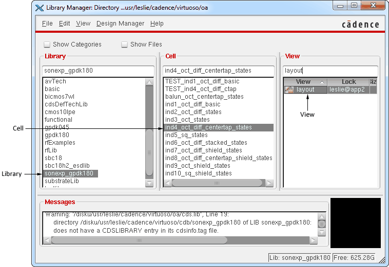
The Library Manager is updated with a list of cells. We will only be using one of the cells for this tutorial: ind4_oct_diff_centertap_states.
The View list in the Library Manager is updated.

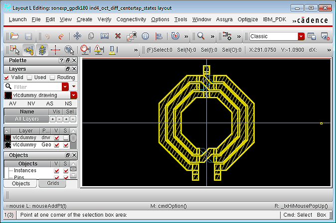
The layout view of the ind4_oct_diff_centertap_states cell appears on your display.

This command loads the Sonnet interface and needs to be used in any layout window in which you wish to use the Sonnet Cadence Virtuoso Interface. The Sonnet menu appears in the main bar of the layout window as shown below.

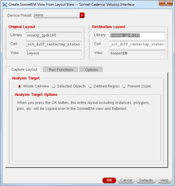
The Create SonnetEM View dialog box appears on your display. You must create a SonnetEM view in order to run a Sonnet simulation on your layout. This way the original layout is not affected. Also, when using only a part of your original layout, it is easier to determine exactly what you are analyzing by having a separate SonnetEM layout.

This dialog box displays the source used to create the SonnetEM view. The view of the resulting cell is also displayed. You may choose to use the same library and cell name or enter the desired Library name in the Library text entry box and the desired cell name in the Cell text entry box in the Destination Layout section of the dialog box. The default for both of these fields are the library and cell of the originating layout. We will be using these default settings.
The Analysis Target section of the dialog box allows you to select what part of the source cell you wish to include in the resulting SonnetEM view cell. The default is the whole cell view. In that case, everything in the source cell is translated into the SonnetEM view. Since we are using the default of the whole cell view, there is no need to change the radio button selection.
The example circuit we are using for this tutorial is a center tapped inductor. Choosing this preset defaults the settings in the Cadence Virtuoso Interface to the most common settings suitable for analyzing a center-tapped inductor. If any of the settings are not the values you wish to use for your analysis, they may be changed in the interface before running your simulation.

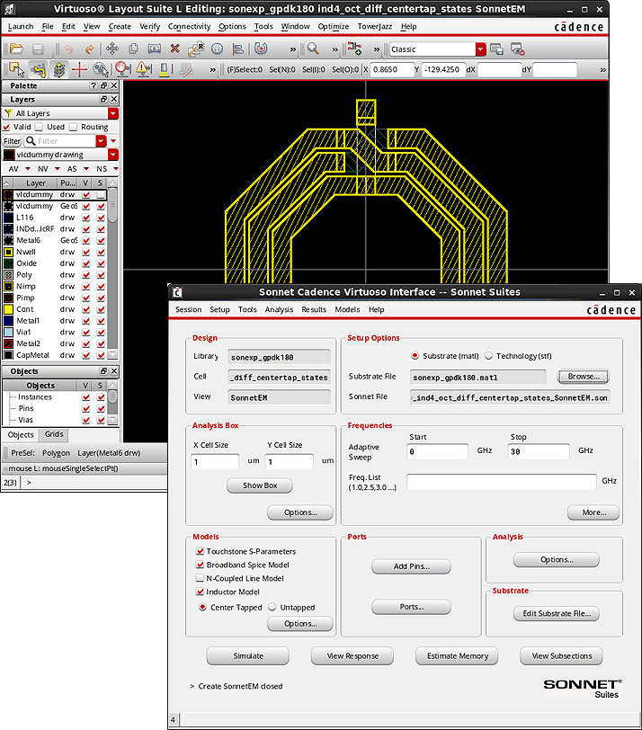
A new layout window appears which displays the SonnetEM view as well as the Sonnet Cadence Virtuoso Interface. The Sonnet Cadence Virtuoso Interface dialog box allows you to control all aspects of the analysis setup and simulation.

 If you are not able to complete the tutorial in one sitting, use the Session - Save State command in the Cadence Virtuoso Interface before exiting. Then, you may access the Sonnet Cadence Virtuoso Interface by opening the SonnetEM view, launching the Sonnet menu (Launch - Sonnet) in the Virtuoso Layout window containing the SonnetEM view, then selecting Sonnet - Open Interface Application. Use the Session - Load State command to restore your previous progress.