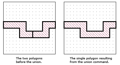
This command allows you to merge polygons in your circuit. You may either select the polygons you wish to merge, then select Edit - Boolean Operations - Union from the main menu of the project editor or select the command, then select the polygons. You may also click on the Union icon in the Edit tool bar.
If the selected polygons have the same loss, and are assigned to the same Technology Layer (if applicable), i.e. the same metal types, then the polygons are merged as shown in the example below. On the left are shown the two selected polygons you wish to merge. On the right is shown the resulting polygon of the Union command.
Note that while metal polygons are used throughout the examples in this topic, these rules also apply to merging via polygons and dielectric bricks, although you may not perform a union command on different types of polygons, such as metal and dielectric bricks.

If the polygons have different properties, such as loss, then the union is not performed and an error message is issued.
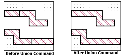
There is no limit to how many polygons you may merge with one command, but the polygons must be in contact with each other for the union command to have any effect. In the example pictured below, all four polygons use the same metal type, but not all the polygons are touching. Therefore, the union command resulted in two polygons instead of one. If all four polygons were touching, the union would have resulted in one polygon. If none of the selected polygons overlap, then the union is not performed and a warning message is issued.
. 
If the multiple polygons use different metal types, then those using the same metal type are merged while polygons of different metal types are not merged. Pictured below is an example of a union command on polygons of mixed metal types. In this case, all four polygons were in contact, but did not all have the same loss. Therefore, the union command left polygon 1 and 2 unchanged; they appear as polygons A and B on the left. Polygons 3 and 4 have the same loss and after the union appear as Polygon C. A warning message is issued.

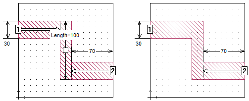
Note that any objects attached to a polygon such as ports, dimensions, reference planes and parameters are removed during a Union command if any of the vertices to which they are attached are removed as the result of the union command. This is demonstrated in the graphic below. The three polygons in the original circuit on the left are merged into the single polygon shown on the right. The reference plane for Port 1 was removed since it was linked to a vertex that was eliminated by the union command. This was also true for the dimension parameters.
.