This tab in the Add/Edit Variable dialog box controls the Interpolation options for the variable being edited or defined. The Add/Edit Variable dialog box is opened when you click on the Add or Edit button on the Variables page of the Circuit Settings dialog box.
Interpolate this variable: Select this checkbox if you wish to be able to use this variable for interpolation. When interpolation is enabled, a set of values is defined at which the analysis engine, em, performs a full electromagnetic simulation. For all other values, em performs a linear interpolation to calculate the response.
When this checkbox is selected, the Auto and Manual radio buttons below are enabled.
Reference: This sets the starting point for the set of values at which a full simulation if performed. In the case of dimension parameters, this allows you to ensure that the values fall on grid, so that the analysis is as accurate as possible as explained in the example below.
Resolution: This defines the delta between values at which a full simulation is performed.
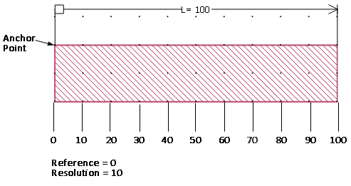
In the example shown below, the cell size is 10 x 10 mils and the variable L is defined as 100 mils. The polygon as entered is directly on grid, so the anchor point of the dimension parameter falls on grid. For this case, we use a reference of 0. With the resolution set to 10, the values for L would be 10, 20, 30, 40 50 etc up until the maximum value. 
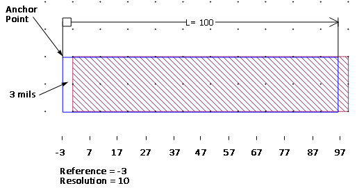
In the second case, shown below, the entered polygon, highlighted in blue is shifted 3 mils to the left. In this case the anchor point is off grid. For this case, we use a reference of -3. With the resolution set to 10, the values for L would be 7, 17, 27 etc up until the maximum value. 