Sonnet can be used to model many different types of coplanar waveguide lines, but each type is modeled differently in Sonnet. This technical tip describes the different modeling techniques for the most common types of coplanar waveguide lines.
Any transmission line with three coplanar conductors, where the center conductor is fed 180 degrees out of phase with the two outer conductors, can be considered a coplanar waveguide line.
Ungrounded Coplanar
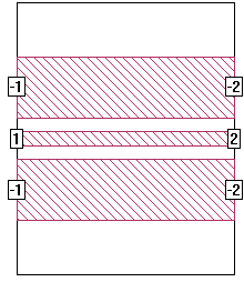
The most common type of CPW is called "ungrounded coplanar," where there is no metal under the substrate. A simple example is shown below and is available in the Sonnet examples.
Notice that the ground ports have been labeled with a negative number (e.g. "-1"), while the signal ports are labeled with positive numbers (e.g. "1"). This represents a balanced port. Any number of ports can have the same positive or negative labels. This is done in the project editor by selecting the ports in question and opening the Port Attributes dialog box by selecting Object - Port Properties. Em sums the total current going into all the positive ports with the same port number and sets that equal to the total current going out of all the ports with that same negative port number. Thus the name "balanced", or "push-pull," port.
Note that we end the width of the ground lines just before they would have touched the sidewall. If the side of the ground line touches the side wall, it shorts out to the sidewall, thus allowing ground current to return via the sidewall instead of through the ground line. This defeats the purpose of the balanced port. Be sure that your ground lines touch the sidewall only at the location of negative port numbers when using balanced ports.
The current density view of coplanar structures may show high current on the outside edge of the ground strip. This is caused from the fact that the infinite ground of an ideal coplanar line is truncated to a finite ground strip. Using a wider polygon to represent the ground strip will reduce this effect, however analysis times will increase. Generally, if the width of the ground strip is 3 or 4 times the gap size, current on the outside edges has only a small effect on the results.
Different Types of Coplanar Waveguide
The following is a list of some of the more popular configurations:
1. Ungrounded Coplanar: No metal on the bottom of the substrate (discussed in the section above).
2. Grounded Coplanar: The bottom of the substrate has a metal ground plane which is electrically connected to the two outer conductors.
3. Floating Coplanar: Metal exists on the bottom of the substrate, but it is not connected to the two outer conductors. Thus the bottom metal is electrically "floating" at a different potential from the two outer conductors.
4. Infinite Coplanar: The two outer conductors are considered infinitely wide. Usually, there is no metal on the bottom of the substrate (case #1), but any of the above three configurations can have finite or infinite outer conductors.
5. Shielded Coplanar: Outer conductors are shorted to the side-walls of a rectangular waveguide. Thus, all four sides of the waveguide are at the same ground potential as the coplanar outer conductors. Waveguide dimensions are part of the design.
Push-pull ports can be used to simulate only some types of coplanar waveguide. Push-pull ports are created by re-numbering the ports on the outer conductors of the coplanar line to a negative number. For example, if the center conductor is "1", then the two outer conductors should each be numbered "-1".

Since the two outer ports have the same port number, they are electrically connected together. Creating the two -1 ports now redefines port 1 such that the voltage on port 1 is now measured with respect to the two -1 ports.
Another way to think of this is that the positive terminal of the generator is connected to the center conductor (port 1) and the negative terminal is connected to the two -1 ports. You may also think of port 1 as your "signal" and the two -1 ports as your "ground".
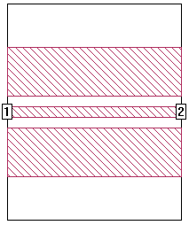
Another method of modeling CPW is shown below:

This method does not use ports on the two outer conductors, so the voltage of port 1 is measured with respect to the six sides of the Sonnet box. If the sidewalls of the box are far away, then this means port 1 is measured with respect to the bottom of the box (assuming the top of the box is also far away).
Therefore, the method you use to simulate your coplanar line depends on how you are exciting it. Each of the above cases should be simulated differently:
1. Ungrounded Coplanar: Add an extra air layer under the dielectric to move the bottom of the Sonnet box far enough away so it has no effect. The sidewalls of the box should also be moved far away (at least several line widths). If the sidewalls and box bottom are far away, using push-pull ports should give the same answer as shorting the outer conductors to the box wall.
2. Grounded Coplanar: Do not use push-pull ports. Just connect the two outer conductors to the sidewall of the box (the same sidewall to which the center conductor is connected). This electrically connects them to the metal ground plane on the bottom of the substrate.
3. Floating Coplanar: Use push-pull ports because the metal on the bottom of the substrate is not connected to the two outer conductors.
4. Infinite Coplanar: Since the two outer conductors are considered infinitely wide, this cannot be simulated with Sonnet. However, you can approximate this case by truncating the two outer conductors to a finite width. Do not use push-pull ports unless you have a floating coplanar line as described in #3. Instead, connect the ground conductors to the box sidewall without ports. This is because the error introduced by truncating the outer conductors can be partially compensated for by allowing the current that should have traveled on the outside edge of the outer conductor to travel through the box sidewalls.
5. Shielded Coplanar waveguide: In this case, create the Sonnet box to be the same dimensions of your coplanar waveguide box. Do not use push-pull ports. Instead, connect the ground conductors to the box sidewall without ports.