Sonnet can be used to compute even mode and odd mode (also called differential mode) impedances and phase velocities for symmetrical coupled lines. To do this, you must create two projects - one which represents the even mode, and one which represents the odd mode.
Odd Mode Project
The odd mode is one in which two conductors are driven differentially, i.e., with identical but opposite polarity signals. To create the odd mode project, start with a four-port coupled line circuit like the one shown below:
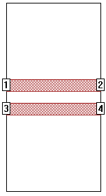
You can create the metal pattern of this circuit by simply drawing two rectangles of the desired dimensions, or by using the Parallel Lines standard geometry element (Insert - Metal). Notice that the lines are placed precisely in the center of the box. This is not necessary in many cases, but we suggest you do this to force the symmetry between the two lines.
For an odd mode excitation, you need to renumber the ports to +1/-1 and +2/-2 as shown below:
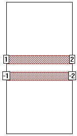
To renumber a port, right-click on the port and select Port Properties. This opens the Port Properties dialog box where you can change the port number to a negative value.
The +/- numbering forces all current going out of port +1 to come back through port -1. Thus the -1 port acts as a "Ground" for port +1. This is the same as if you replaced the +1/-1 combination with a single voltage source with the positive terminal connected to one polygon and the negative terminal connected to the other. This configuration is sometimes call "push-pull" because the current is "pushing" into port +1 and "pulling" out of port -1. The resulting Z0 and Eeff (effective dielectric constant) values represent the odd mode Zo and Eeff. See Interpreting Z0 and Eeff later in the topic for more details.
Even Mode Project
The even mode is one in which two conductors are driven with identical same polarity signals. To create the even mode project, renumber the ports to +1/+1 and +2/+2 as shown below:
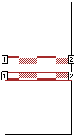
The +/+ numbering forces the magnitude and phase of the voltage at the two ports to be the same. If the structure is symmetrical, the current is also the same. This is often called an "even" mode. The resulting Z0 and Eeff values represent the even mode Zo and Eeff. See Interpreting Z0 and Eeff later in the topic for more details.
Using Symmetry to Improve Efficiency
You can improve the efficiency of both the even and odd mode simulations by taking advantage of the symmetry in the circuit. Using symmetry allows the analysis engine to analyze only half the circuit. This requires only one-half the amount of metal, thus saving you up to a factor of four in memory (since the size of the moment matrix is proportional to N2 where N is the number of subsections) and up to a factor of 8 in analysis time (since the analysis time for the solving of the moment matrix is proportional to N3).
Even Mode Symmetry: Even mode symmetry can by used any time the voltage on one side of the line of symmetry is equal to the voltage at the corresponding location on the other side of the line of symmetry. This is exactly what we have with the even mode of a symmetrical coupled line structure. Therefore, we can use even mode symmetry. This is accomplished in Sonnet by selecting the "Symmetry" checkbox under in the Box page of the Circuit Settings dialog box (Circuit - Settings). in the project editor. This places a dashed line of symmetry through the middle of your circuit:
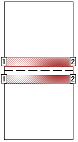
This even mode line of symmetry is sometimes called a "magnetic wall" (because the magnetic field is zero in the plane of symmetry). When the analysis engine sees the line of symmetry, it ignores all metal below the line of symmetry and only solves for the metal above the line of symmetry- thus using less memory. Once the analysis engine has solved for the top half of the circuit, a mirror image of the results is added below the line of symmetry, without requiring any additional analysis time. Notice that this implies that you could actually delete the metal below the line of symmetry, or add additional metal below the line of symmetry, and the analysis results (and analysis time/memory) would not change.
Odd Mode Symmetry: Odd mode symmetry can by used any time the voltage on one side of the line of symmetry is equal and opposite to the voltage at the corresponding location on the other side of the line of symmetry. This is exactly what we have with the odd mode of a symmetrical coupled line structure. Therefore, we can use odd mode symmetry. This is accomplished in Sonnet by using the Sonnet metal box wall as the plane of symmetry. This plane is sometimes called an "electric wall" (because the electric field is zero in the plane of symmetry). This means that if you want two coupled lines separated by a spacing of "S", you create a single line and place it a distance of S/2 from the electric wall.
You could drag one of your existing lines down (or up) toward one of the box walls to use electric wall symmetry. However, here is a simpler way to do it. The first step is to change the Y box dimension using the Box page of the Circuit Settings dialog box (Circuit - Settings):
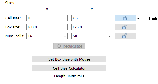
You should first "lock" the cell size as shown above, then decrease the Y box size by a factor of two. In the above example, the Y box size was originally 250.0 and it was changed to 125.0. If the original circuit was placed symmetrically in the box, this action moves the bottom box wall up to desired plane of symmetry.

The above circuit will not run properly because the lower line and ports are outside the Sonnet box. So the second step of setting the electric wall is to delete the bottom line. The finished circuit would look like this:

The differential impedance, Zdiff, is defined as the impedance measured between two conductors driven differentially (identical signals with opposite polarity, also known as odd mode). Odd mode impedance, Zodd, is the impedance of a single conductor in a differential pair. The relationship between the two impedances is Zdiff = 2*Zodd1.
The common mode impedance, Zcommon, is defined as the impedance in two conductors driven with identical, same (even or common mode) polarity signals. Even mode impedance, Zeven, is the impedance of either conductor when both are driven with identical, same polarity signals. The relationship between the two impedances is Zcommon = Zeven/2
You should use caution when viewing the even/odd mode impedances generated by the techniques described above. The following table shows the relationship between the Sonnet definition and the impedance definitions above:
Odd Mode |
Z0 |
Eeff |
Sonnet Using +1/-1 Ports |
Zdiff |
Eodd |
Sonnet Using Electric Wall Symmetry |
Zodd |
Eodd |
Even Mode |
Z0 |
Eeff |
Sonnet Using +1/+1 Ports |
Zcommon |
Eeven |
Sonnet Using Magnetic Wall Symmetry |
Zcommon |
Eeven |
Interpreting the S-parameters
S-parameters are not quite so straightforward. You may need to multiply or divide the Z-parameters by two, which, for S-parameters, is equivalent to multiplying or dividing the normalizing impedance by two. You might not need to change them at all (as would be the case for coplanar lines). It all depends on your definition of even and odd modes.
To convert S-parameters from Sonnet using an electric wall to get the same results as you would with using odd mode (+1/-1) ports:
1) If you haven't already analyzed, you can set the ports to 25 ohm ports using the project editor. Sonnet will calculate odd mode 50 ohm S-parameters, but if you plot the response, the terminations will say "25 ohms". You should interpret the plot as if it were 50 ohms. If you decide to export the S-parameters to a file, the header line in the file will also say 25 ohms. To fix this, save the file using 25 ohms, then edit the response file using a text editor and change the header to say 50 ohms.
OR
2) If you have already analyzed your circuit, you probably used 50 ohm ports (the default). If you plot the S-parameters, the response view will show you 50 ohm S-parameters by default. But because you are using odd mode symmetry, the S-parameters you see are really 100 ohm S-parameters. To see 50 ohm S-parameters, you need to change the terminations to 25 ohms. Now the graph will say "25 ohms", but you are really viewing 50 ohm S-parameters. If you decide to export the S-parameters to a file, the header line in the file will say 25 ohms (assuming you changed your terminations to 25 ohms). To fix this, edit the output file and change the header to say 50 ohms. Do not attempt to change your terminations to 50 ohms and then assume the exported file will be correct.
Note that you may not need to perform the above steps, depending on your definition of the odd mode.
For the even mode, Sonnet gives the same S-parameters whether you are using push-push ports or the magnetic wall symmetry. However, you still may need to re-normalize your S-parameters depending on your definition of the even mode.