The Advanced Subsectioning Options dialog box is opened when you click on the Advanced button in the Subsectioning Options section of the Analysis Options dialog box. The controls are detailed below.
Maximum Subsection Size: Sonnet’s analysis engine uses a variable subsection size. Small subsections are used where needed, such as around corners, and larger subsections are used elsewhere. This reduces the size of the matrix which must be inverted, often providing a dramatic increase in the speed of an analysis. In no case are the subsections smaller than a single cell.
This field allows you to limit the maximum size of the subsection, generated by the analysis engine, in terms of subsections per wavelength. The default of 20, used when this option is not on, is fine for most work and means that the maximum size of a subsection is 18 degrees at the highest frequency of analysis. Increasing this number decreases the maximum subsection size until the limit of 1 subsection = 1 cell is reached.
Estimated Epsilon Effective: Normally, the analysis engine engine has an algorithm which estimates the effective dielectric constant used to determine the wavelength used for maximum subsection size. If this option is selected you may override the automatic algorithm and force the solver to use your dielectric constant to calculate the wavelength which is used in setting the Maximum Subsection Size. If this option is not on, Auto appears in the text entry box to indicate that the analysis engine engine is using its algorithm to determine the subsectioning frequency.
Polygon Edge Checking: Normally em considers one adjacent metal level in either direction from the present level when computing the subsectioning. This is an important consideration when thin dielectric layers are used. Polygon Edge Checking allows you to override the automatic algorithm and specify how many adjacent levels or Technology Layers should be considered when calculating subsections. You select the type of edge checking you wish to use, Level or Technology Layer, from the drop list which is enabled when you select this checkbox. Note that entering a value of zero causes em to only look at the present metal level.
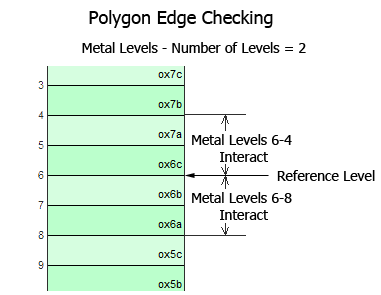
Level: If you select level, then the number of levels you enter are checked in either direction. For example, as shown below, if polygon edge checking is set to 2, then using level 6 as the reference level, levels 6-4 would interact in the upward direction and levels 6-8 in the downward direction.
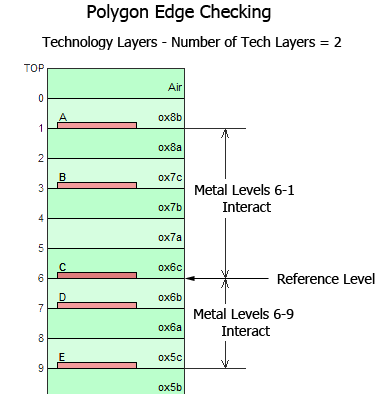
Technology Level: If you select Tech. Layers, then the number of adjacent Technology Layers you enter is checked in either direction. Metal levels which do not use Technology Layers are not included in the count but if a metal level is in between levels with Technology Layers, then polygon edge checking is done on that metal level as well.
For example, as shown below,polygon edge checking is set to 2. Using Level 6 as the reference level, Technology Layer C and Technology Layer A (metal levels 6-1) interact and Technology Layer C and Technology Layer E (metal levels 6-9) interact.
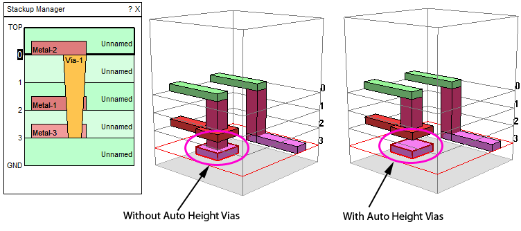
Auto Height Vias: Normally vias extend from the specified starting metal level to the specified ending metal level. If the auto height vias option is selected, then a via will terminate if its path, starting from the upper metal level and extending downward, contacts planar metal. For example, if you define a via from metal level 3 to metal level 0 and there is a planar polygon in its path on level 2, then the via is terminated on level 2 and therefore extends from level 0 to level 2. Note that the via is depicted in both the 2D and 3D view as the actual metal which will be analyzed. However, the associated Via Technology Layer still appears unchanged in the stackup since other vias associated with the Technology Layer may still extend the fully defined length as shown below.
Only polygons which completely cover the cross sectional area of the via are guaranteed to affect the height of the via. Note that planar metal that is on an intervening metal level but does not intersect the path of the via does not affect the height of the via.
Choose Subsection Frequency based on: The analysis engine uses the subsectioning frequency to calculate the wavelength which is used in setting the Maximum Subsection Size. The subsectioning frequency is determined by the drop list described below:
XMin, XMax, YMin, YMax: Sonnet allows you to control how cells are combined into subsections for each polygon. This is done using the parameters “X min”, “Y min”, “X max” and “Y max.” These fields are applied as a global setting for all polygons. For a detailed discussion of these parameters and how they affect subsectioning in Sonnet, please refer to "Changing the Subsectioning of a Polygon" in the Subsectioning chapter of the Sonnet User’s Guide.
Use Edge Mesh: When using the Edge Mesh option, all Manhattan polygons (no diagonal edges) are treated as if they were non-Manhattan polygons. In other words, the edge subsections are always one cell wide regardless of X Min or Y Min. This field is applied as a global setting for all polygons. When used in conjunction with large X Min or Y Min values, this option can be very useful in reducing the number of subsections but still maintaining the edge singularity. This is very often a good compromise between accuracy and speed.
Conformal Mesh Subsection Length: You may set a maximum length for a conformal section by selecting this checkbox and entering the desired length in the text entry box below. This is useful in reducing the size of your conformal sections to ensure higher accuracy. The default length of a conformal section is 1/20 of the wavelength of the subsectioning frequency.
All Metal Fill: This field allows you to set the fill type for all metal polygons in the translated project. If you do not wish to set a global fill type, select “<off>” from the drop list. If you wish to set a fill type, choose from Staircase, Diagonal or Conformal. For more information on fill types see the Metalization Properties dialog box.
All Via Fill: This field allows you to set the fill method for all vias in your translated project. If you do not wish to set a global fill method, select “<off>” from the drop list. If you wish to set a fill method, choose from Ring, Vertices, Center, Full and Bar. For more information on via fill methods, please see the Via Properties dialog box.