This section of the dialog box may be used to increase the box size in Sonnet and to set the reference planes. Sonnet’s em has an automatic de-embedding capability. When invoked, em removes the port discontinuity and a desired length of transmission line. The reference planes instruct em as to the desired length of the transmission line to be removed. One reference plane length per box side may be specified.
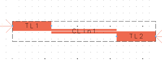
Adding a margin moves the box wall out that distance from the bounding box for the circuit being translated. A feedline from the ADS port is added to the circuit and a reference plane is set for the length of the feedline if the port is defined as a box wall port. You may see the box in the Layout window while you are changing the margin if Show Box is selected. The outline appears in blue.
Default Margins
When you initially open the Analysis Box dialog box for a layout, the margins are set to the default value entered in the Sonnet Preferences dialog box (Sonnet ⇒ Preferences). If you have changed the margins and wish to restore the default values, click on the Default Margins button in the Analysis Box dialog box.
Changing the Margins
To change the margins of your box, do the following:
- If the Sonnet box is not presently visible, click on the Show Box button in the Sonnet Analysis Box dialog box to show an outline of the box in your layout view.
The boundaries of the box appears as a blue line in your layout view. If all the margins are set to zero, the box outline coincides with the bounding box of the ADS layout as shown below. Note that some of the colors in the ADS pictures have been changed to provide more clarity in this documentation.
- Enter a value of “25” in each of the Margin text entry boxes.
The Analysis Box dialog box should appear similar to the illustration below The outline of the box in the layout has not changed because the margin values entered have not yet been applied to the layout.
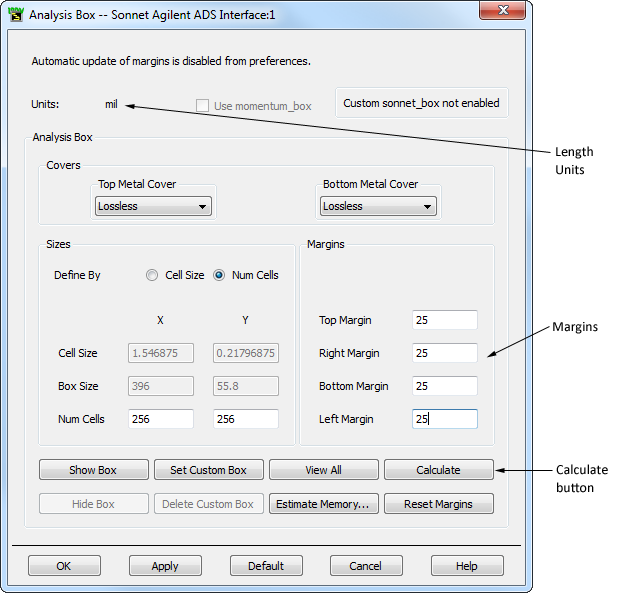
- Click on the Calculate button or the Enter key to update the layout view.
This will move the box wall 25 mils on the right, left, top and bottom wall. Since mils are presently the length unit, a value of 25 causes the box wall to move 25 mils. Notice that the box outline in the layout view has moved 25 mils in each direction.
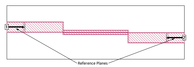
Shown below is the same circuit translated into Sonnet’s project editor. Notice that the reference planes are 25 mils long and the feedline was automatically added when the margins were enlarged.