A config view uses the model symbol to refer to a specific model produced by a Sonnet simulation. That view can then be used in running simulations in Cadence Virtuoso, allowing you to use your Sonnet EM results in your netlist simulation. The config view also allows you to easily switch between models, if more than one model was created in your Sonnet simulation.
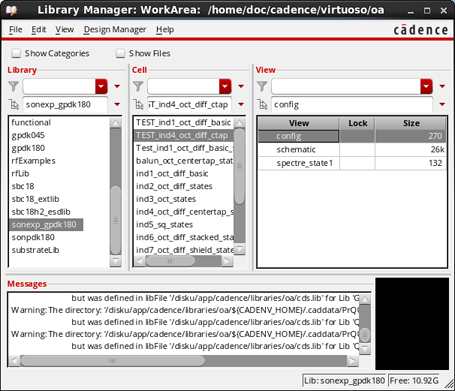
The Open Configuration or Top Cellview dialog box appears on your display. There are two elements to the configuration view, the schematic and the configuration. The dialog box defaults to opening both.
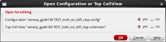
The schematic is opened for the test bench and the Hierarchy Editor is opened for the configuration.
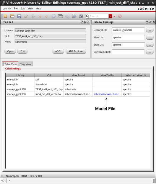
The Hierarchy Editor defines which view to use for the symbol in the test bench schematic. You created three different models during your simulation. By using the symbol in the test bench, you may easily switch between model types by modifying the View to Use. The inductor model is presently selected (this was done for the purposes of the tutorial in order to demonstrate switching models.)
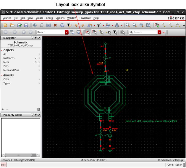
When the symbol is used in the test bench, the model used will be the Touchstone S-Parameters model created during your Sonnet analysis.
This saves which model will be used in the config view. With the Touchstone S--parameters selected in the configuration, you are ready to simulate the test bench circuit.
This updates the schematic with the new information from the Hierarchy Editor so that the test bench schematic is referencing the proper model.
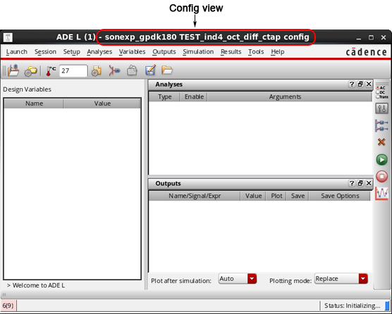
The Virtuoso Analog Design Environment appears on your display with the test bench loaded as the design. The name of the config view appears in the title bar.
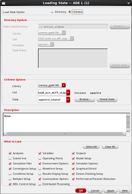
Loading the state performs the setup for the simulation which was included in the example file. The Loading State dialog box appears on your display.
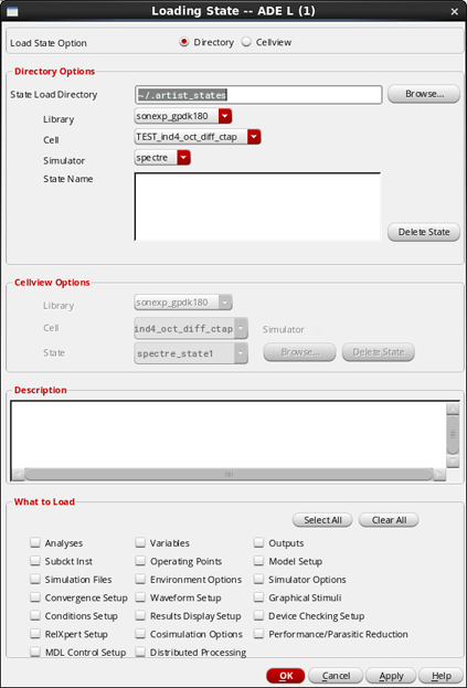
The Cellview Options section of the dialog box is enabled, with the state spectre_state1 already selected. The bottom of the dialog box lists the elements included in the state.
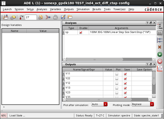
The ADE L window is updated and should appear similar to the picture below.
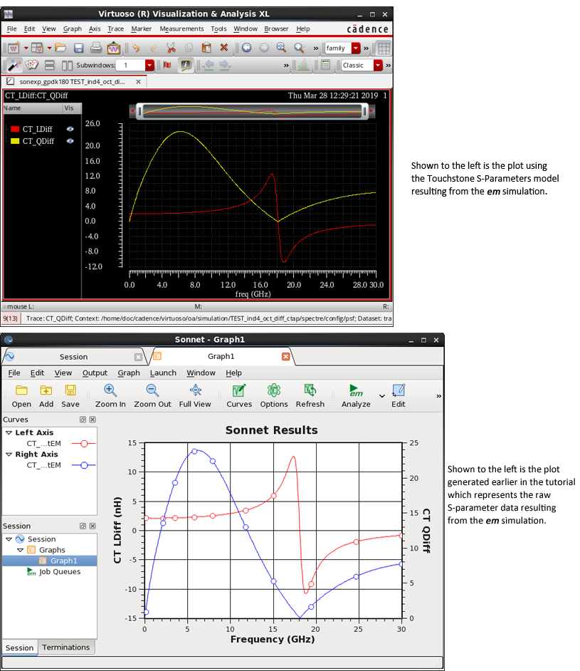
You can also click on the green Run button on the right edge of the ADE L window to start the simulation. An output window appears on your display and is updated while the simulation runs. Once the simulation is complete, a plot of the results is opened. Similar to the plot you set up at the end of the EM simulation earlier in the tutorial, this plot also displays the inductance and the Q factor. However, this plot represents the Touchstone S-Parameters, whereas the previous plot represented the raw S-parameters. If you compare the two plots, you can see that they are virtually identical, showing the Touchstone S-Parameters model accurately represents the original S-parameters.
This completes the Sonnet Cadence Virtuoso Interface tutorial.