A via to ground can be added from any metalization level. This example shows a rectangular via; the same steps would apply to a circular or polygon via; you would just use the appropriate command for that shape of via. To add a via to ground, go to the level from which you wish the via to extend downwards and perform the following:
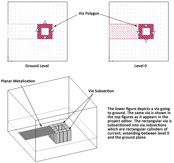
The via polygon metalization is shown on Level 0. Note that the arrows are pointing down, indicating the direction of the via. Since this via uses the Ring meshing fill, the center of the via does not contain metalization but is filled with the dielectric of the dielectric layer. The ground level is completely metallized; however, the subsectioning of the via is displayed on the ground level to indicate that there is a via metalization in the layer above.
If the via to ground is added when there are multiple intervening metal levels between the present level and ground, the via polygon can be seen on each level. The intervening levels have via arrows pointing in both directions to indicate that the via extends both upward and downward. Below is shown a rectangular via polygon extending from metal level 0 to ground in a three level circuit.
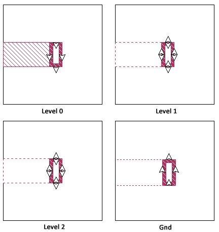
The via shown above extends from level 0, the highest metal level in the circuit down to the ground level. The via arrows on the rectangular via on level 0 point only in the downward direction. The via polygon appears on levels 1 and 2 in the same position but with via arrows pointing in both the upward and downward position indicating that the via extends in both directions from these levels. The via polygon is drawn on the ground plane to indicate its position with the via arrows pointing upward indicating that the via extends upward. Since the complete ground plane is metalization, the via polygon is drawn simply as a reference for the user.