Conformal Meshing is applied as a property of a metal polygon or a property of a Metal Technology Layer. The following example shows how to set conformal meshing in a project which does not have any Metal Technology Layers defined. The process is very similar for a Technology Layer; you would edit the meshing properties of the Technology Layer.
To use conformal meshing for a polygon, do the following:
- Select the desired polygon(s) by clicking or lassoing.
The selected polygons are highlighted.
- Select Object ⇒ Metal Properties from the main menu.
The Planar Polygon Properties dialog box appears on your display.
- Select “Conformal” in the Fill Type drop list.
- Click on the OK button to apply the changes and close the dialog box.
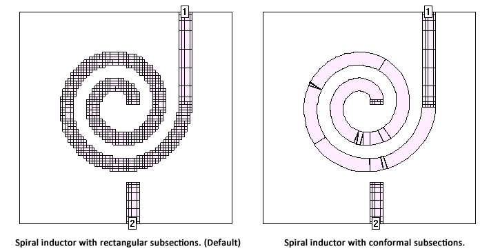
The polygon does not appear any different in the circuit. To see the difference, you need to use the View- Subsections command. Shown below is the subsectioning for the same spiral inductor. The circuit on the left uses rectangular subsections and the one on the right uses conformal subsections. Note that the rectangular subsectioning uses a much higher number of subsections for the spiral inductor than does the conformal meshing. Rectangular subsectioning was used for the feedlines in both cases.
If you chose Conformal meshing, then the subsectioning controls in the Planar Polygon Properties dialog box - Xmin, Ymin, XMax, YMax and Edge Mesh - are disabled and ignored.