The Array via loss model is used to represent an array of small solid vias by approximating the entire array as a single large via. Usually, this is done to reduce the processing resources necessary to analyze the circuit, as having many small vias is computationally expensive. The Array via loss model is most often used for computing the loss of via arrays which have been simplified when translating a circuit into a Sonnet project. In those cases, the Via metal type is automatically created. You may also use this loss model to manually create a via metal type if you wish to model a single via in the project editor that represents an array in your final design.
NOTE For a detailed discussion of array simplification, please see Via Array Simplification.
Like the Volume model, it is a frequency-dependent model which takes into account the 3D characteristics of the via array. The only difference between the Volume model and this model is the method by which the cross-sectional area is computed. With the Volume model, the cross-sectional area is computed based on the wall thickness or solid setting. For the Array model, the cross-sectional area is computed using the Fill Factor or Density which is based on the original via array.
The Fill Factor is a loss parameter when using conductivity or resistivity to define the loss. The Fill Factor is a percentage indicating how much of the cross-sectional area of the original via array is metal-filled. The Fill Factor is calculated by summing the areas of all the individual vias in the array and dividing that by the total area of the array, defined as the bounding box which surrounds all the vias in the array. The result is multiplied by 100 to convert to a percentage. An example of an array and how to compute it’s fill factor is shown below.
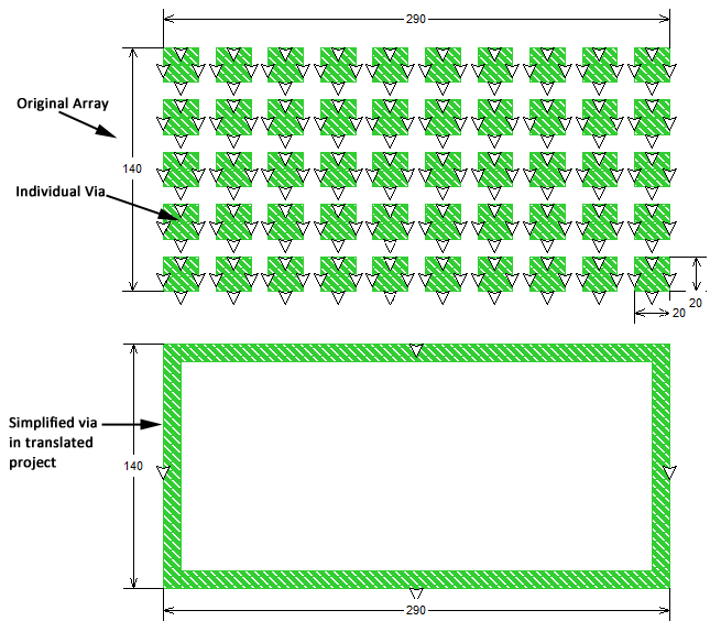
The array, shown on top, consists of a 5 by10 array of 50 individual vias whose cross section is a 20 micron by 20 micron square. Therefore the sum of the areas of all the individual vias is 50 * 400 = 20,000 square microns. The total cross-sectional area of this array is 40,600 square microns (290 microns * 140 microns). This provides a Fill Factor of 49.3% ((20,000/40,600) * 100). The converted simple via modeled in Sonnet is shown on the bottom. Although the total cross sectional area of the simplified via is 40,600 microns, the Array loss model is set such that the calculated DC loss for the via is based on the loss of the actual metal in the array, (40,600 * 0.493 = 20,015.8) i.e., the 20,000 square microns.
NOTE: When translating circuits into Sonnet, if there are two or more arrays which use the same metal but whose fill factors differ significantly, two or more via metal types are created in the Sonnet project. For example, there are two arrays, one with a fill factor of 50% and another of 75% both using a metal named “viametal1.” The translated project will contain two via metal types called “viametal1_1” and “viametal1_2.”
The loss for the Array model may also be defined using the Resistance Per Via. Resistance Per Via for the array model represents the vertical (Z) resistance in Ohms of an individual via within the via array. As discussed above, the array of vias is modeled as a single, merged via polygon, but the loss for that simplified polygon is based on the actual metal present in the array.
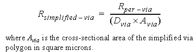
The loss parameters of this simplified via polygon are Resistance Per Via (Rper_via) in Ohms/via and Via Density (Dvia) in vias per square micron. The total resistance in Ohms of the simplified via polygon is constant with frequency and is computed as follows:
The horizontal loss at DC and RF for the Array model is infinite.