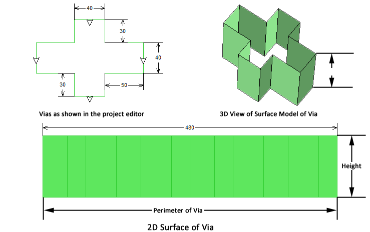
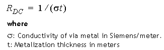
The surface via loss model treats the via as an infinitely thin hollow tube giving it a 2D surface as pictured below.
This method allows you to enter three values: RDC, RRF and XDC. The first parameter, RDC, determines loss at low frequency (where the conductor is much thinner than the skin depth).
The equation for RDC is:
The second parameter is the skin effect coefficient, RRF. At frequencies above DC, em uses the same surface impedance equation used by Sonnet for planar metal [15]. This equation includes the skin effect, resulting in a smooth transition from DC to high frequencies. The equation for RRF is:
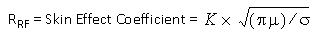
where:
σ: Bulk conductivity in Siemens/meter
t: Metalization thickness in meters
μ=μ0 x μr
μr = relative permeability of your metal, which is typically 1.0 for most metal materials. Magnetic materials, such as nickel, have a μr greater than 1 and therefore significantly decrease the skin depth.
K: A value between 0.5 and 1.0 and depends on the current ratio. For a detailed discussion of current ratio see Current Ratio. Shown below is a table of K values for typical applications:
Application |
Recommended k values |
Symmetrical Stripline |
0.5 |
Coplanar Waveguide signal lines |
0.6 |
Microstrip signal lines |
0.6 |
Polygon ground planes |
1.0 |
Analysis box covers |
1.0 |
The third parameter is Xdc, the surface reactance, and is normally set to zero. This parameter is provided for advanced users who want to customize the surface impedance of the metal.
The horizontal loss at DC and RF for the Surface model is infinite.