A node is used in a netlist to connect two elements. If an element is a geometry project with multiple internal ports, as is the case with co-calibrated ports, nodes are assigned in the netlist to each port. In larger circuits, with multiple co-calibrated ports, the netlist can be quite complex, so an example is shown below of performing circuit subdivision of a large circuit with co-calibrated ports. The resulting netlist and subprojects will be examined to illustrate how the ports in the geometry subprojects are assigned to nodes in the netlist which is created when the circuit subdivision is performed. For a complete explanation of Circuit Subdivision, please refer to Circuit Subdivision.
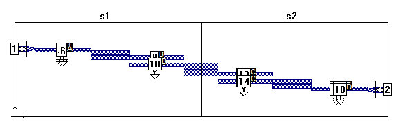
The full circuit, cocal_netlist.son, which contains 18 ports, is pictured below with a subdivider. There are 16 co-calibrated ports, each group consisting of four ports in the interior of the circuit. The subdivider is set so that the full circuit will be subdivided into two geometry projects, each containing half of the full circuit. When the circuit is subdivided, a netlist is created which connects the two geometry projects together into a circuit equivalent to the full geometry project. When the netlist is analyzed, each geometry subproject is analyzed and then those simulation results are used to simulate the response of the netlist circuit.
Once the subdivision is performed, three new projects are created. The netlist, cocal_netlist_net.son, the S1 subproject, cocal_netlist_s1.son, and the S2 subproject, cocal_netlist_s2.son. The netlist is shown below. Note that the main network has 18 ports, the same number as the original project before splitting it. For the main network, the node number and port number are identical.
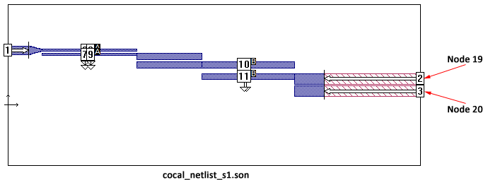
The third line of the netlist shows the Project Element which defines the inclusion of the geometry subproject cocal_netlist_s2.son. Show below is the Edit Element dialog box for the subproject displaying the correspondence of netlist nodes to circuit ports. Also shown is a view of the subproject with both the corresponding ports and nodes labeled. When you add an element to a netlist, each port defined in the element is assigned to a node in the netlist. The Edit Element dialog box will contain a text entry box for each port in the element. You enter the desired node number for the port in that port’s text entry box. In the case of a circuit subdivision, this assignment of nodes is done automatically by the software.
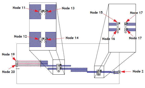
Note that there are two nodes, 19 and 20, which appear in the project elements, but are not part of the main network which uses nodes 1 through 18. Nodes 19 and 20 are used to connect ports 2 and 3 of cocal_netlist_s1.son to ports 1 and 2 of cocal_netlist_s2.son. These were the ports added to the circuit when it was subdivided. Connecting these ports by using the same netlist nodes makes the netlist circuit equivalent to the original circuit before subdivision.