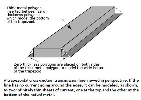
In this section, we use a combination of thick metal and Normal (zero thickness) metal to approximate thick metal lines where the vertical cross-section has an arbitrary geometry. To demonstrate this capability, we use a simple trapezoidal geometry, the cross section shown in the figure below.

To create the thick metal trapezoid, set up the dielectrics so that there is one layer of dielectric with the same thickness as the thick metal. Then, place a polygon representing the top side of the thick metal on the bottom side of that dielectric layer using one of the physically thick planar metal models. Make this polygon as thick as the dielectric layer. Then place two polygons to extend the bottom side of the thick metal to the desired width on the bottom side of that dielectric layer. These polygons should use the Normal model for the metal type, which is modeled as a zero-thickness metal.

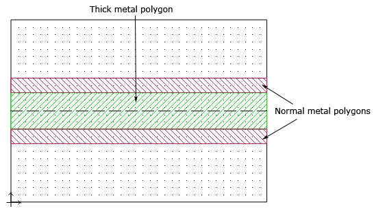
The wide bottom of the trapezoidal line is made up of the thick metal polygon with a Normal metal polygon on either side. These polygons are using a zero thickness metal and used to expand the bottom surface area of the trapezoidal line to the desired width.

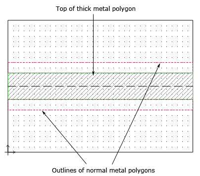
Pictured above is the thick metal polygon as seen on the metal level above. Since the thick metal polygon is the same thickness as the dielectric layer, the metal also appears on this level. Only the outlines of the zero-thickness metals are shown on this level.
Next, place any desired ports on the thick metal polygon, not on the thin metal polygon. Since the thick metal polygon is placed adjacent to the two zero-thickness polygons, all three are connected electrically and the port is across all polygons.