As discussed in Metal Fill, em subdivides the circuit into subsections which are made up of “cells,” the building block in the project editor. The following discussion describes how to select a cell size. To access the Cell Size calculator, click on the Cell Size Calculator button in the Box page of the Circuit Settings dialog box, which is invoked when you select Circuit - Settings from the project editor menu, and click on Box in the sidebar menu of the Circuit Settings dialog box which appears.
 When possible, find a common factor for your most critical dimensions.
Since your circuit geometry is snapped to the nearest cell, you should set your cell size to be a common factor of your most critical dimensions. For example, if your circuit has dimensions of 30 microns, 40 microns and 60 microns, possible cell sizes are 10 microns, 5 microns, 2.5 microns, 2 microns, etc. Large cell sizes result in more efficient analyses, so 10 microns is best if analysis time is an issue. For complex layouts, the largest common factor that exactly matches all your dimensions may be too small to be practical. In such cases, you should use Sonnet's Cell Size Calculator to determine the optimal cell size based on your most critical dimensions.
Calculate the X cell size and the Y cell size independently.
The X cell size and Y cell size do not have to be the same number. Calculate the X cell size based on just your dimensions in the X direction, and your Y cell size based on just your dimensions in the Y direction.
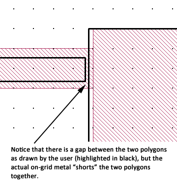
![]() Visually inspect the metal fill (indicated by the fill pattern) for potential problems.
Visually inspect the metal fill (indicated by the fill pattern) for potential problems.
Once a common factor is found, some of your less critical dimensions may not be a multiple of this factor. You should inspect your circuit for potential problems caused by polygons which are not exact multiples of this cell size. The Connectivity Checker can also be of use to find unintended short circuits or open circuits. An example is shown below.
 Adjust cell size for level of accuracy required
A smaller cell size results in a more accurate but slower simulation. So there is a trade-off between speed and accuracy. The accuracy of most circuits depends on the number of cells across the width of the transmission lines in your circuit. The more cells across the width, the more accurate the results. For example, a transmission line which is only one or two cells wide results in an error in the characteristic impedance of about 5-6%. For smaller cell sizes, the following equation1 can be used:
The example, "Stripline Benchmarks," includes a spreadsheet and Sonnet project files which was used to verify the above equation.
Notice that for NW > 2, each time you halve your cell size, the error is also halved. For example, you chose a cell size of 6.0 microns based on the largest common factor between all your critical dimensions. Your smallest line width is 12.0 microns. This means your smallest line will be two cells across the width, resulting in 5-6% error in Z0. Based on the above equation, changing your cell size from 6.0 microns to 3.0 microns (four cells across the line width) results in about 4% error in Z0. You could decrease your cell size even further to 2.0 microns which would decrease your error to about 2%.
Select a cell size that is smaller than 1/20 of a wavelength.
Most circuits require that your cell size be 1/20 of a wavelength or smaller. Larger cell sizes usually result in unacceptable errors due to incorrect modeling of the distributed effects across the circuit. The analysis engine will issue a warning if your cell size is larger than 1/20 of a wavelength at your highest frequency. However, you may wish to calculate this value yourself before you analyze your circuit. If you do, estimate your effective dielectric constant when calculating a wavelength or use the highest dielectric constant in your circuit.
1 J. C. Rautio, "An Ultra-High Precision Benchmark For Validation Of Planar Electromagnetic Analyses," IEEE Tran. Microwave Theory Tech., Vol. 42, No. 11, Nov. 1994, pp. 2046-2050.