In the example presented in Inserting Modeled Elements into a Geometry, a pair of co-calibrated ports was placed at each location in the em circuit layout where a modeled element would eventually be inserted. It is also possible to perform the same analysis using delta gap ports, because each resistor in this example is a series modeled element without access to ground. Any time access to ground is not required for a modeled element, you can replace the pair of co-calibrated ports with a single delta gap port.
The figure below shows a geometry project for the T attenuator with delta gap ports at each modeled element location. Note that the gaps between polygons at these locations have been removed. This is because you must attach delta gap ports between two abutted polygons. This slightly impacts the overall performance of the attenuator.
The network file shown below connects the desired resistors across the ungrounded-internal ports of the circuit shown above. Since delta gap ports do not have access to ground, only a single node is specified when connecting an element across them.
 Delta gap ports have one terminal connected to an edge of a polygon and the second terminal connected to an abutted edge of a second polygon. Delta gap ports do not have access to ground. Therefore, only 1-port elements or 1-port networks may be connected across delta gap ports. Resistors, capacitors, and inductors are technically one-port elements and therefore, may be inserted in place of an delta gap port in a netlist.
The netlist for this circuit, att_lumped2.son, is shown below. Both the geometry project, att_lgeo2.son, and this netlist are available in the Att example for Netlist Project Analysis.
An important feature to notice in this netlist is the use of parameters. Three parameters, Z3, Z4 and Z5 have been defined in the netlist project and their values used for the three resistor modeled elements. Parameters are defined in a netlist on the Variables page of the Circuit Settings dialog box (Circuit - Settings) in the project editor. Z3 and Z4 are equal to 16.77 and Z5 is equal to 67.11.
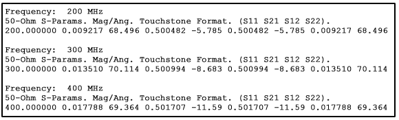
The listing below shows the S-parameter results obtained from the analysis with delta gap ports. These results are very similar, but not identical, to the results for co-calibrated ports. The differences are primarily due to the change in the gap size between polygons at the points where lumped elements are inserted.