Inductor Model
The Inductor Model is only available if you have purchased a Broadband SPICE Extractor license from Sonnet. Please see your system administrator if you are unsure of the availability of this feature.
The Inductor Model Extractor (IME) feature allows you to extract an intuitive equivalent circuit model from the EM analysis of a spiral inductor. It has proven most effective with spiral inductors on a conductive substrate, such as those usually found in RFIC processes involving lossy silicon substrates.
Model Topologies
There are two topologies available for the Inductor model: the Untapped model and the Center Tapped model. Both topologies generate a simple, physical, fixed-topology circuit model.
Untapped Topology
Shown below is the schematic of the Untapped inductor model topology.
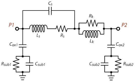
The inductor must have at least two ports. Ports 1 and 2 must be the input and output ports of the inductor. If you include any additional ports, the algorithm assumes that you will be connecting them to ground in your circuit simulator. Thus, you may connect ports to a patterned ground shield or ground ring if you wish.
Center Tapped Topology
Shown below is the schematic of the Center Tapped inductor model topology.
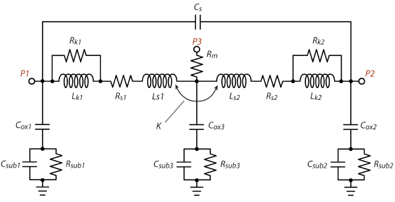
The inductor must have at least three ports. Ports 1 and 2 must be the input/output ports, and port 3 must be the center-tap port. If you include any additional ports, the algorithm assumes that you will be connecting them to ground in your circuit simulator. Thus, you may connect ports to a patterned ground shield or ground ring if you wish.
Creating the Model File
We recommend using an ABS sweep with a start frequency of 0.0 and a stop frequency equal to or higher than twice the frequency at which the maximum Q-factor is found. Since this topology is not meant to be used above the self-resonance frequency, any data above the self-resonance frequency is ignored.
There are two methods you may use to generate an Inductor Model file: automatic, and interactive.
Automatic
You may set up your project so the EM solver will automatically generate the file after the EM simulation is complete. From the Project Editor, select Circuit > Settings > [Output Files] and then select Add File > Inductor Model. Choose which topology you want, and set any options you wish. For details on the Inductor Model options, see Options.
Interactive
After simulating your project, you may generate an Inductor Model from a Sonnet graph by following the steps below.
Select a curve representing the desired project.
Select Output > Inductor Model File.
Choose your topology from the Topology drop-down list.
The topologies are explained in the Model Topologies section above.
Change any options you wish to change.
There are Basic and Advanced options. For details on the Inductor Model options, see Options later in this topic
Click the Extract button
This creates the output model file. A Model Schematic window appears on your display with the schematic for your topology displayed including the calculated values for your model. An example is shown below.
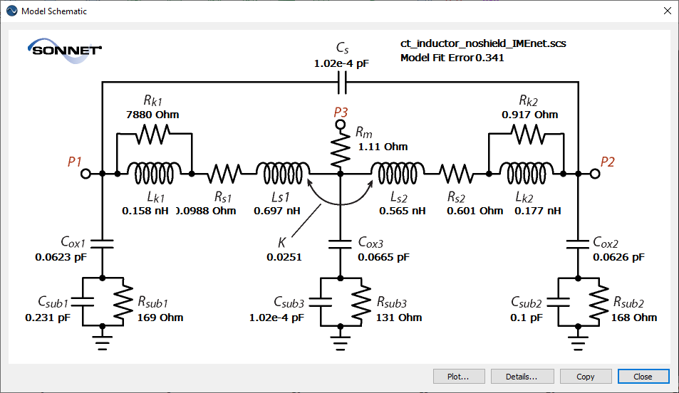
You may click the Copy button to copy the schematic image to your clipboard where it is available to paste into other programs.
You may open the Details window by clicking the Details button in the Schematic window.
The Details window displays a report on the model created.
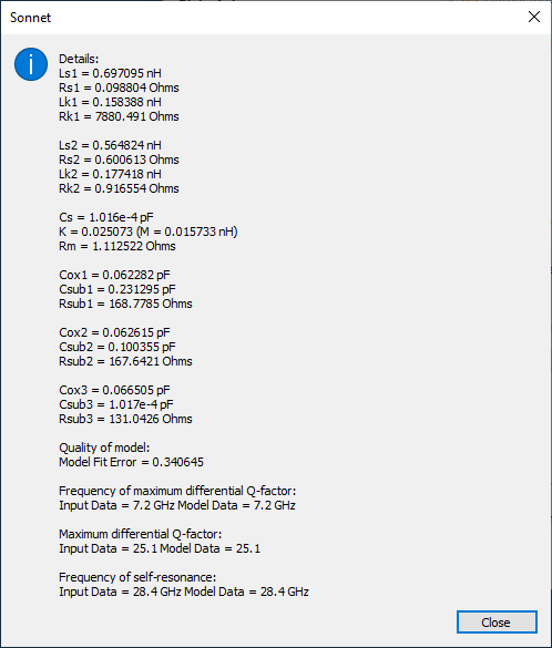
You may click the Close button after viewing the details.
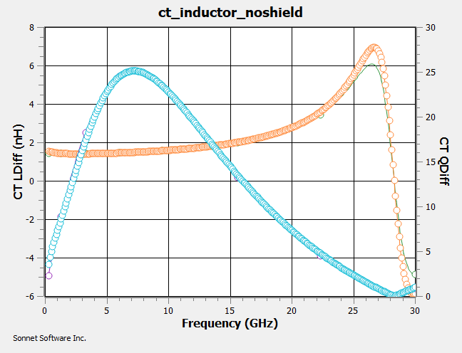
You may click the Plot button in the schematic window to open a comparison plot.
This plot shows the inductance and Q-factor of both the original data and the data generated using the extracted model. In the example below, the extracted model agrees well with the original data at frequencies below the self-resonance frequency.
Options
You may obtain a short description for each option by hovering your mouse over the option in any dialog box. See the descriptions below for those options which require additional information.
Predicted File
By default, the predicted S-parameter data upon which the model is based is output to a file. This allows you to visually check the accuracy of your model when it is complete. The base name of the file ends with the text "_modeled" and is located in the same folder as your Inductor Model file. If you do not wish to create a predicted file, click the Advanced button, and unselect the Generate predicted S-parameter file checkbox.
Optimization Band
This section of the dialog box only appears if Center Tapped is selected as the Topology. Enter the frequency band over which you wish to optimize your inductor model by entering the starting frequency of the band in the Start text entry box and the ending frequency in the Stop text entry box. If you wish the software to automatically calculate the optimization band, select the Auto checkbox. If this checkbox is selected, then the optimization band will be f(Qmax) +/- 10%, where F(Qmax) is the frequency where the maximum Q occurs.