Derived Tech Layers
A Derived Tech Layer is a Tech Layer where metal or Dielectric Bricks are automatically generated, based on a rule involving one or two source Tech Layers. The polygons of the source Tech Layers are left unmodified, or you may specify that it be deleted. When an EM analysis is performed, the EM solver processes the Derived Tech Layers before starting the analysis (see also Enabling/Disabling).
Results of Derived Tech Layers are not shown in the Project Editor's 2D or 3D views. However, you can select File > Export Flattened Project. This command processes the Derived Tech Layers and Precedence and creates a new project file so you can preview the results.
Projects that contain both Derived Tech Layers and Dimension Parameters may produce unexpected results. We recommend previewing the flattened project before analyzing it.
You create Derived Tech Layers by selecting Circuit > Settings > [Tech Layers]: Derived Layers. You may then click the Add Planar, Add Via, or Add Brick button to add a Planar, Via, or Brick Tech Layer respectively.
The properties of a Derived Tech Layer may be entered by clicking the Edit button. You also specify a rule for the the Derived Tech Layer as explained below.
Rules
A Derived Tech Layer performs an operation on the polygons found on the source Tech Layer(s). The operation can be a boolean operation or a sizing operation.
Boolean Operations
AND
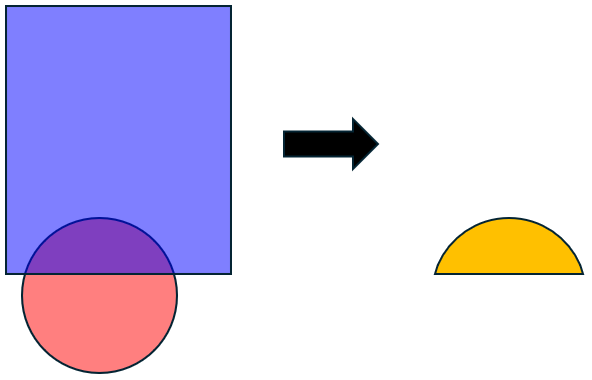
The AND operation results in the intersection of the polygons. Shown below is an example. The left side shows the two source Tech Layers and the right side shows the resulting Derived Tech Layer using the AND operation.
OR
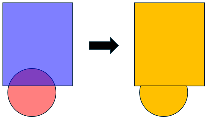
The OR operation results in the union of the polygons. Shown below is an example. The left side shows the two source Tech Layers and the right side shows the resulting Derived Tech Layer using the OR operation.
You may select the Overlapping polygons only checkbox to include only polygons that overlap. Non-overlapping polygons will not be included.
DIFF
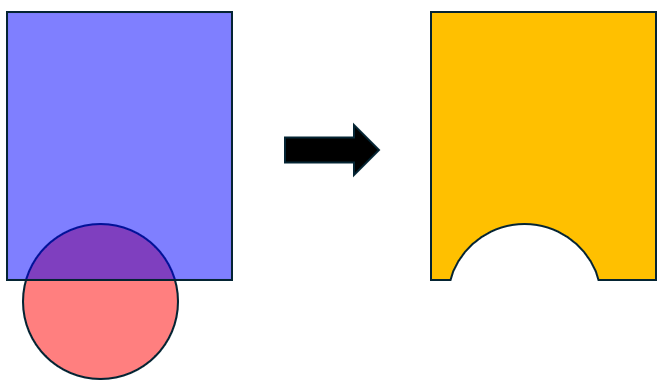
The DIFF operation is order dependent. It subtracts the second source Tech Layer from the first. Shown below is an example. The left side shows the two source Tech Layers. The Derived Tech Layer, shown on the right, subtracts the bottom circle from the top rectangle.
You may select the Overlapping polygons only checkbox to include only polygons that overlap. Non-overlapping polygons will not be included.
XOR
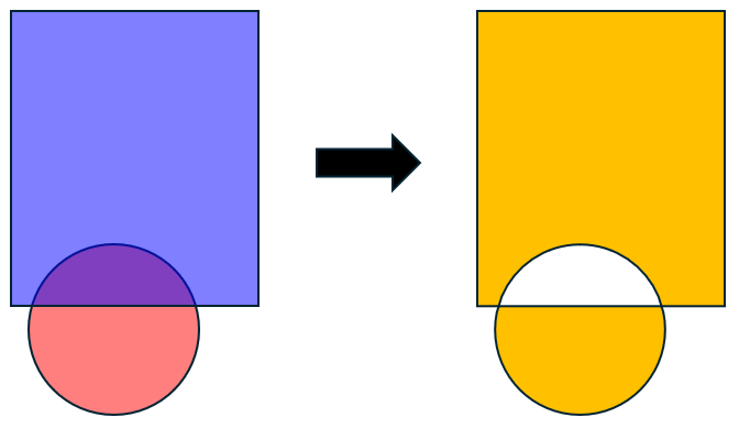
The XOR (exclusive OR) operation results in the union of the polygons, excluding any intersecting area. Shown below is an example. The left side shows the two source Tech Layers and the right side shows the resulting Derived Tech Layer using the XOR operation.
Sizing Operations
Sizing operations take a single Tech Layer and a Distance value. The resulting Derived Tech Layer is a duplicate of the original Tech Layer, but is either larger or smaller than the original.
GROW
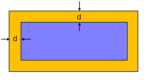
The GROW operation increases the size of the polygons in the original Tech Layer by a specified distance. The specified distance is added to every edge. Shown below is an example. The inner rectangle is the original Tech Layer and the outer rectangle is the Derived Tech Layer, where "d" represents the specified distance.
SHRINK
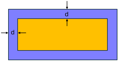
The SHRINK operation decreases the size of the polygons in the original Tech Layer by a specified distance. The specified distance is subtracted from every edge. Shown below is an example. The outer rectangle is the original Tech Layer and the inner rectangle is the Derived Tech Layer, where "d" represents the specified distance.
Remove After Flatten
For many situations, you may not want a source Tech Layer to remain after the flattening process. To remove a Tech Layer and its associated polygons after flattening, select the Remove after flatten checkbox next to the source layer in the Derived Layer Rule dialog box. All polygons using the deleted Tech Layer will be deleted.
If there are objects such as Dimension Parameters, ports, or linked reference planes attached to the deleted polygons, they will also be removed after flattening.
Enabling/Disabling
By default, Derived Layers are processed by the EM solver. You may disable this feature by selecting Circuit > Settings > [EM Options]. Then click > Advanced to expand the Advanced section and unselect the Process derived layers checkbox.
Multiple Derived Layers
If your project has more than one Derived Layer, they are processed in order, starting at the top of the list. You may use the ![]() Move Up and
Move Up and ![]() Move Down buttons to change the order the Derived Layer rules are processed.
Move Down buttons to change the order the Derived Layer rules are processed.