The Advanced Subsectioning tab on the EM Options page of the Circuit Settings dialog box allows you to control the subsectioning of your circuit by the analysis engine, em. Since subsectioning has a direct effect on processing time and accuracy, this allows the experienced user a measure of control over the trade off between them.
WARNING: Be aware that these are advanced options and should not be changed from their default values except by an experienced user who understands the effects of these options.
Maximum Subsection Size: Em uses a variable subsection size. Small subsections are used where needed, such as around corners, and larger subsections are used elsewhere. This reduces the size of the matrix which must be inverted, often providing a dramatic increase in the speed of an analysis. In no case are the subsections smaller than a single cell.
This field allows you to limit the maximum size of the subsection, generated by the analysis engine, in terms of subsections per wavelength. The default of 20, used when this option is not on, is fine for most work and means that the maximum size of a subsection is 18 degrees at the highest frequency of analysis. Increasing this number decreases the maximum subsection size until the limit of 1 subsection = 1 cell is reached.
See also Metalization Properties dialog box for specifying the minimum and maximum subsection size for an individual polygon.
Estimated Epsilon Effective: Normally, em has an algorithm which estimates the effective dielectric constant used to determine the wavelength used for maximum subsection size. If this option is selected you may override the automatic algorithm and force em to use your dielectric constant to calculate the wavelength which is used in setting the Maximum Subsection size.
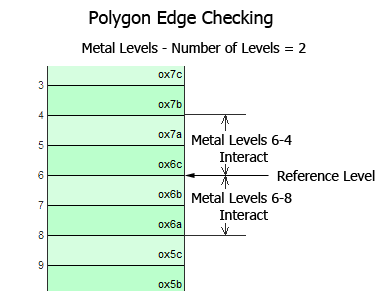
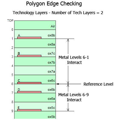
Polygon Edge Checking: Normally em considers one adjacent metal level in either direction from the present level when computing the subsectioning. This is an important consideration when thin dielectric layers are used. Polygon Edge Checking allows you to override the automatic algorithm and specify how many adjacent levels or Technology Layers should be considered when calculating subsections. You select the type of edge checking you wish to use, Level or Technology Layer, from the drop list which is enabled when you select this checkbox. Note that entering a value of zero causes em to only look at the present metal level.

For example, as shown below,polygon edge checking is set to 2. Using Level 6 as the reference level, Technology Layer C and Technology Layer A (metal levels 6-1) interact and Technology Layer C and Technology Layer E (metal levels 6-9) interact.

Auto Height Vias: This setting causes a via to terminate when it encounters planar metal in its path. For more information, see Auto Height Vias.
The analysis engine, em, uses the subsectioning frequency to calculate the wavelength which is used in setting the Maximum subsection size. The subsectioning frequency is determined by the radio buttons described below:
Present and Previous Analyses: This is the default setting for the subsectioning frequency. Select this option if you wish to analyze your project at the highest frequency used in this or any previous run of the project.
Present Analysis Only: In this case, the highest frequency at which the project is analyzed for this run is used to subsection the circuit.
Previous Analyses Only: Select this option if you wish to analyze your project in a different frequency range than a previous run but wish to use the same subsectioning on your circuit. The maximum frequency from all previous runs on this project will be used as the subsectioning frequency.
Use Fixed Frequency: Select this option to enter the frequency you wish to use for the subsectioning frequency. Enter the desired frequency in the text entry box to the right which is enabled when this option is selected. This frequency will be used as the subsectioning frequency for all analyses of this project.