You need to specify the parameters for the ports to be used in Sonnet. You define the Sonnet ports by adding Virtuoso pins to your SonnetEM view which are converted to Sonnet ports. All pin types, with the exception of symbolic, may be used in Virtuoso. Pins can be converted to standard box-wall ports, co-calibrated ports, delta-gap ports or via ports.
For this tutorial, your pins will be converted to standard box-wall ports. For a discussion of the other port types, please see Ports in the Sonnet User's Guide.
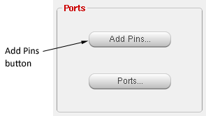
You may wish to zoom in on the feed lines of the inductor before adding the pins. To define the ports for your design, do the following:
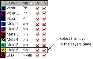
You want to draw the pin on the same drawing layer where you wish to attach the Sonnet port to the metal trace. The metal traces for the inductor are drawn on “Metal6” so we also want to place the pins on Metal6.
The Create Shape Pin dialog box appears on your display.
These names identify the pins. You may enter any character string for the terminal names. We are using P1, P2 and P3 since these pins are going to be converted to Port 1, Port 2, and Port 3 in the translated Sonnet project.
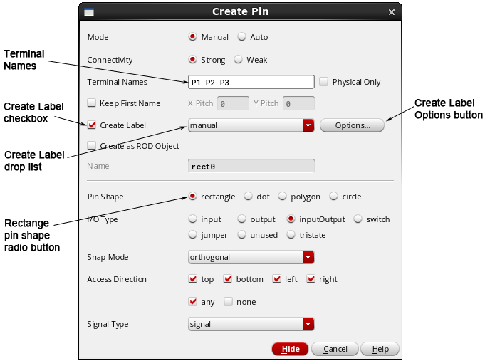
For the best translation of pins into the Sonnet environment, we recommend using a shape pin of the type “rectangle.”
Displaying the pin label in the layout window is optional. For the tutorial, we will display the pin label. Selecting this checkbox allows you to also place a label on the pin when you are adding it in the layout window.
This allows you to control the appearance and placement of the labels.
The Set Pin Label Text Style dialog box appears on your display which allows you to control the appearance of the terminal name in the layout window.
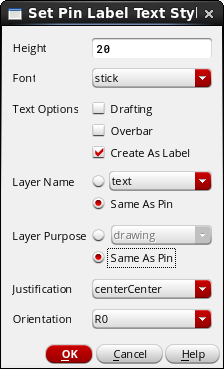
This ensures that the label is large enough to see in the layout window.
This ensures that label appears on the same drawing layer as the pin.
The pin should be placed across the edge of the metal trace to which you wish the Sonnet port attached. It is not necessary to be overly precise in placing your pin; during the translation, the center point of the pin is snapped to the closest available edge of a polygon. Since this pin is located on the edge of your layout, it is converted to a Sonnet box wall port; if the pin had been on the interior of your layout, it would have been converted to a co-calibrated port.
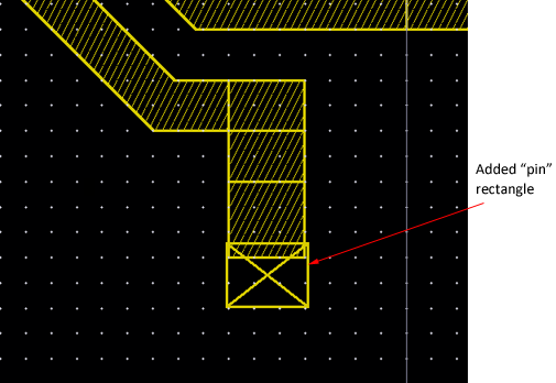
When you complete adding the pin, the label appears.
Your circuit should appear similar to the picture below.
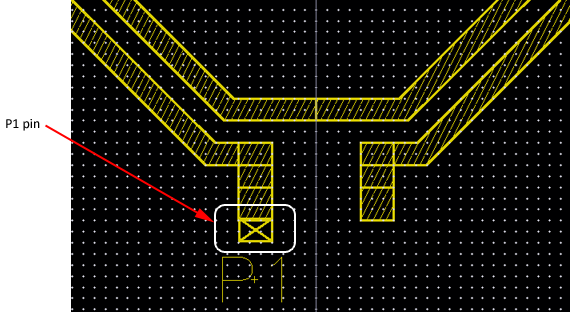
Your circuit should now appear similar to this:
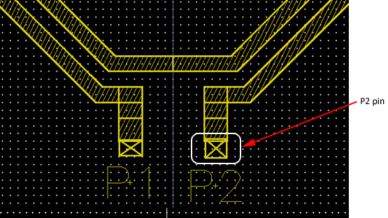
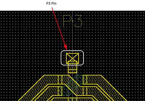
Your circuit should now appear similar to this:
The Ports dialog box appears on your display.
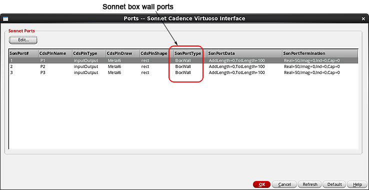
As you can see, the Cadence pins were automatically mapped to Sonnet standard box-wall ports, since they were placed on the bounding box of the circuit.
Since no changes were made in this dialog box, you may use the Cancel button to close it, ensuring that nothing was changed.
The appearance of the cursor changes.
This completes setting up the ports. Next, we will save the changes we have made thus far in the tutorial using the Save State command.