Before the circuit can be analyzed, you must add ports. So the next task is to extend the feedlines to the box walls, add ports and then set reference planes so that the effects of the added feedlines are removed by the de-embedding process. This may all be accomplished by the use of a single command when the feedline is the same width as the polygon to which it will be connected.
De-embedding is the process of calibrating the ports. Each port in a circuit analyzed by em introduces a discontinuity into the analysis results. In addition, any feed transmission lines that might be present introduce phase shift, and possibly, impedance mismatch and loss. De-embedding is the process by which the port discontinuity and feed transmission lines are negated from the analysis results. The process of negating lengths of transmission line during de-embedding is known as “shifting reference planes”. Sonnet defines a reference plane to indicate the length of feed transmission line you wish to have negated during de-embedding. For a full discussion of de-embedding, please refer to De‑embedding in the Sonnet User’s Guide.
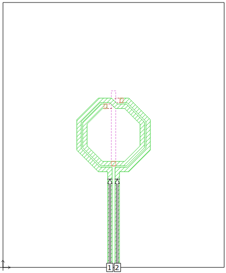
You will add a port and feedline to each of these stubs.

The appearance of the cursor changes to indicate you are in Add Feedline mode.
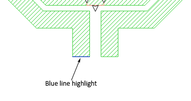
The blue line indicates the polygon edge from which the feedline will be extended to the boxwall.
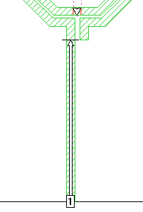
The first feedline, port and reference plane are added to your circuit as shown below. A standard port is added at the end of the feedline on the boxwall with a reference plane set such that it de–embeds the added feedline.
 button in the project editor tool bar.
 This zooms out to a full view of your circuit, which should appear similar to the picture below.
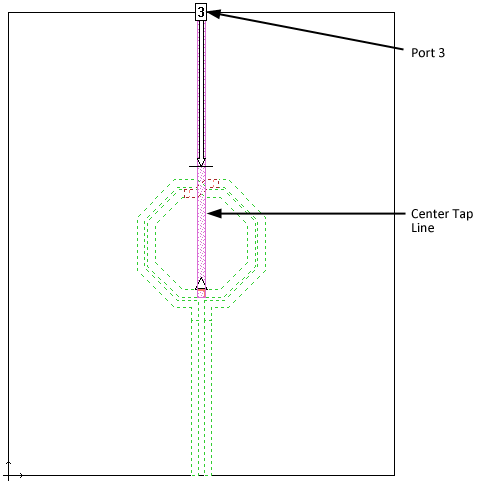
The view updates to level 9. The center tap line is on this metal level.
When you are done, the view on metal level 9 should be as shown below. The length of the reference plane for Port 3 is 300 microns.
This completes the post-import editing.