There are several checks you may wish to do before analyzing your circuit.
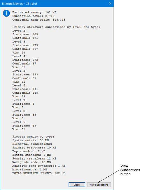
A small message box appears with “Subectioning Circuit” displayed. When the subsectioning is complete, the Estimated Memory dialog box is displayed with statistics on the circuit, including how much memory is necessary to analyze the circuit. When conformal mesh is used, the memory can be significantly reduced out of proportion to the reduction in analysis time. The true time is a function of the subsection total and the conformal mesh cells. So it is possible to have a circuit using conformal mesh that requires the same amount of memory as a circuit without it, but the conformal mesh circuit requires more time. But conformal mesh does reduce the memory requirements and processing time, while achieving the same accuracy, as analyzing the same circuit using staircase fill.
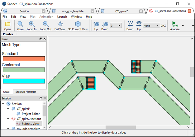
The Subsection Viewer is opened in the Sonnet session window and the Estimate Memory dialog box is closed. This allows you to see the subsectioning of your circuit that will be used for the analysis.
 on the top of the inductor.
 As you can see the areas around the vias are using standard staircase subsections (orange) while the inductor is using conformal subsections (green) where the subsections are larger and conform more closely to the shape of the input polygon. The edges are still a “staircase” shape because the metal fill has to be “on” grid, but the subsections are larger and can be irregular shapes.
The Subsection Viewer is closed.
Since the actual metal analyzed by em is snapped to the grid, occasionally this process could introduce unintended shorts or open circuits. Sonnet provides a Connectivity checker which shows connections between polygons using these snapped dimensions. This allows you to check for shorts or opens introduced in the import. It can also be used to check for general layout problems. For a complete discussion of the Connectivity Checker, please see Connectivity Checker in the Getting Started manual
The circuit is grayed out.
The view is switched to metal level 3 where the majority of the metal in the circuit is placed.
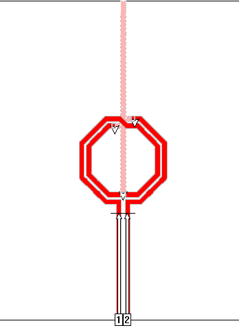
When you click on any polygon when the Connectivity Checker is on, it and any polygon that it is electrically connected to, turn red. As you can see, the complete circuit is red in this case which means there are no opens. Note that metal on other levels than the presently viewed one, are displayed in pale red.
Since the frequency sweep and analysis options were set up in the template file, the circuit is ready to analyze.