Enhanced Resonance Detection Example
This topic is a detailed discussion of the Sonnet example, supercond_resonators, which is composed of several Sonnet projects. The projects are used to demonstrate the Enhanced Resonance Detection setting in Sonnet. The example projects may be accessed using the Example Browser.
Introduction
Adaptive Band Synthesis (ABS) is an efficient way to sweep a Sonnet project and is explained in the Adaptive Band Synthesis topic. The ABS algorithm works well with traditional RF circuits, especially filters. However, superconducting circuits often contain resonators with extremely high loaded Q-Factor, resulting in very narrow bandwidths. In these cases, when the default settings are used, ABS may not completely resolve the resonances or miss them entirely. The following examples demonstrate how the Enhanced Resonance Detection setting can be used to resolve these issues.
Single Resonator Circuit
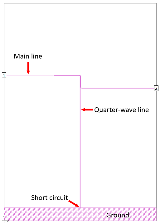
Superconductor resonators use many of the traditional RF resonator structures such as half-wavelength open-circuit transmission lines. The Sonnet example project, 1_QtrWave_SuperCondResonator, is a circuit using a short-circuited quarter-wavelength microstrip line.
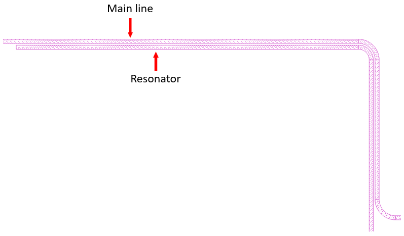
The picture below is a close-up of the region where the resonator couples to the main line. A substantial length of tight coupling is required to produce a significant resonance in the S-parameter curves.
Conductor Material
The circuit uses a niobium conductor material defined using the Surface Impedance Loss Type.
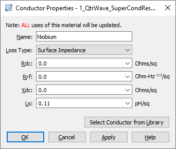
A value is entered for the surface inductance, Ls, to represent the kinetic inductance of the superconductor (see Ls).
Dielectric Material
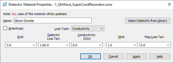
The substrate is 0.75 micron thick silicon dioxide. Since the metal is lossless, the dielectric loss tangent of the silicon dioxide controls the overall loss of the circuit. A small value of 1.0e-5 is entered to approximate the dielectric loss when circuit is cooled to the operating temperature.
Ports
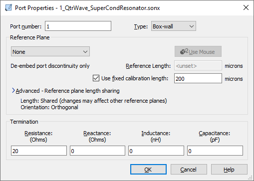
With a 0.75 micron thick silicon dioxide substrate, only low normalization impedance values are practical in the circuit design.The port terminations are set to 20 ohms. In addition, the port uses a Fixed Calibration Length to reduce de-embedding analysis time. See Calibration Standard Length for more details.
Default ABS Sweep
The example project file, 1_QtrWave_SuperCondResonator, uses the default ABS Sweep. The S21 results are shown below. The ABS sweep detected a resonance near 10 GHz and only partially resolved it.
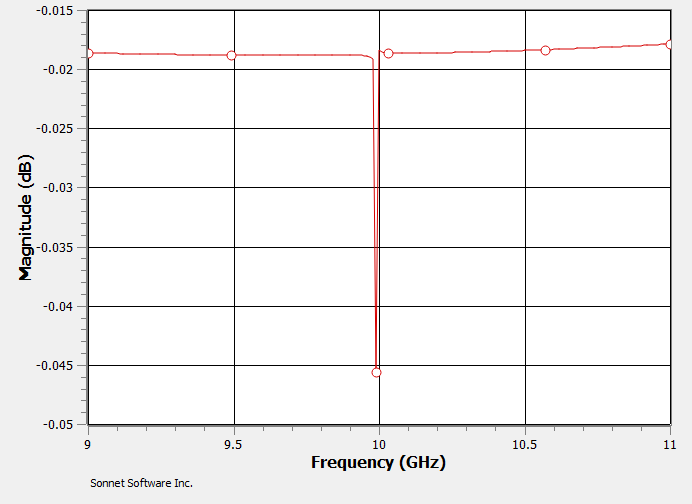
To fully resolve the narrow-band resonance, one or more additional analyses would be required. Each iteration would use a narrower ABS sweep, with a finer ABS frequency resolution until the true curve shape is clear. If the circuit contained multiple resonators, the procedure would have to be repeated for each resonance. The next section describes a better approach using Enhanced Resonance Detection.
Enhanced Resonance Detection
The Enhanced Resonance Detection (ERD) setting adds an intelligent, multi-pass routine to the default ABS algorithm and eliminates the need to run multiple sweeps to locate and resolve high Q-Factor resonances. See Enhanced Resonance Detection for details on the algorithm and how to enable it.
The example project, 1_QtrWave_SuperCondResonator_ERD, has the Enhanced Resonance Detection setting enabled. A close-up of the results is shown below.
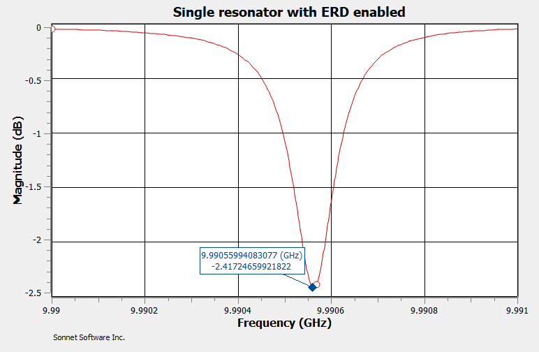
The ABS Sweep with ERD did a nice job with the curve. A Data Marker was also added to demonstrate the fine frequency resolution around the resonance.
Both ERD example projects were simulated using quad precision. Many high-Q circuits require quad precision to avoid numerical error and/or to obtain a highly precise resonant frequency value. See EM Options for details on how to enable quad precision.
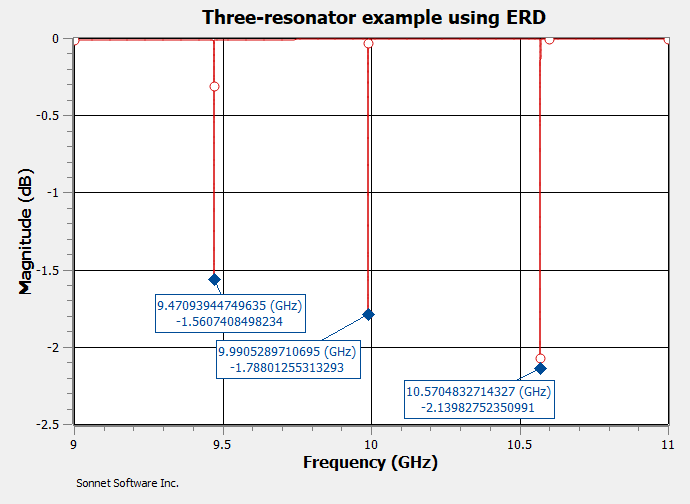
Triple Resonator Circuit
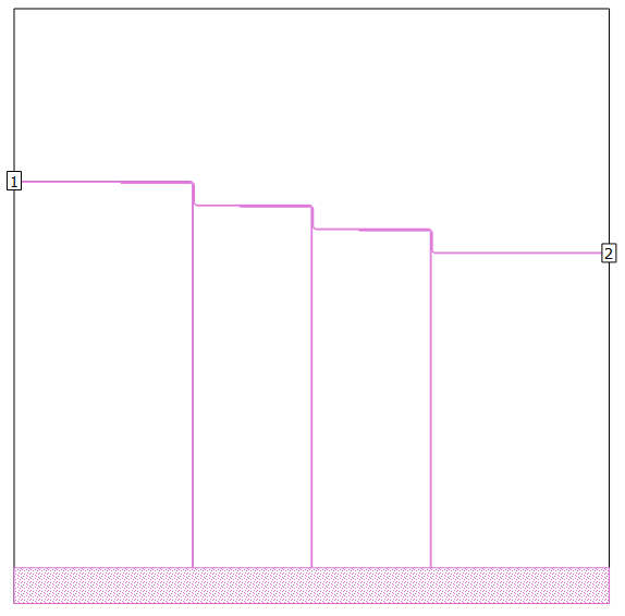
The ERD feature can detect multiple resonances in a single ABS sweep. The Sonnet example project, 3_QtrWave_SuperCondResonators_ERD contains three quarter-wavelength resonators. The center resonator is the same geometry as the single resonator discussed above. A 200 um longer resonator appears to the left, and a 200 microns shorter resonator appears to the right.
When ERD is used, all three resonances are detected and resolved.
Internal testing has shown that ERD performs well with circuits containing 10 or more resonances.