Antennas and Radiation
This topic describes how to model radiation in Sonnet, including radiating circuits and planar antennas, such as microstrip patch antennas and arrays. The following discussion assumes your circuit is an antenna, but the same guidelines may be applied to any radiating structure.
Modeling an Unshielded Environment
The six sidewalls of Sonnet's Analysis Box are perfect electric conductors by default. In order to model radiation in Sonnet, the following guidelines should be considered.
Valid Antennas
Although Sonnet can accurately simulate many planar antennas, an antenna for which the direction of maximum radiation is toward the horizon should not be simulated in Sonnet. If most of the radiation from the antenna is toward the horizon, it will reflect off the sidewalls of the Analysis Box and introduce error.
One example of an antenna for which Sonnet should not be used is one with a significant surface wave. If there is a significant surface wave, it is reflected by the box sidewalls. In general, any surface wave is both reflected and refracted when it encounters the edge of the substrate. This boundary condition is different from the conducting wall of Sonnet's Analysis Box.
Project Setup
The following procedure should be used when setting up your project.
Set the Analysis Box size to be as large as possible.
The Analysis Box sidewalls may be thought of as forming a waveguide whose tube extends in the vertical direction. This setup propagates energy from the antenna toward the top and/or bottom cover of the Analysis Box. Radiation is then approximated as a sum of many waveguide modes. If the tube is too small, there are few, if any, propagating modes. We recommend a minimum box size of four wavelengths plus the antenna size. However, the larger the box, the higher the accuracy because more modes can propagate through the waveguide.
Center your geometry in the Analysis Box.
The antenna should be placed in the approximate center of the box to reduce coupling to the box sidewalls.
Set one or both box covers to Free Space.
By default, the top and bottom covers of the Analysis Box are perfect electric conductors which would reflect any radiation back into your antenna and introduce error. To model radiation, at least one of the box covers must be set to Free Space (Circuit > Settings > [Box] : [Covers]). This acts as an absorber of any radiation.
For example, if your antenna is using one of the covers as a ground plane, then the other cover should be set to Free Space. If you have no ground plane, or if you are using a metal polygon to model your ground plane, then set both covers to Free Space.
Free space has a characteristic impedance of 377 ohms/square. This value is a compromise. All TE modes have a characteristic impedance larger than 377 ohms, while all TM modes are lower and 377. Thus, while a 377 Ohms/square cover does not perfectly terminate any mode, it forms an excellent compromise termination for many modes. As the Analysis Box size increases, both the TE and TM lower order modes approach 377 ohms. Thus, the larger the box, the better the approximation.
Place the Free Space cover(s) outside the fringing fields of the antenna.
The position and distance of the Free Space cover(s) is important. If the absorbing cover becomes involved in the reactive fringing fields which form the near field of the antenna, a reactive input impedance could change into a resistive input impedance, overestimating the radiation loss.
If the box size is small enough such that the waveguide modes are not close to free space (see previous step), then some of the radiation may reflect off the cover(s). This could cause resonances at frequencies where the distance between covers is a multiple of one-half wavelength. Therefore, for relatively small boxes, it is recommended to keep the total cover-to-cover distance to be a little less than one-half wavelength.
To do this, calculate the electrical length of any dielectrics at your highest frequency of interest. Then set your air dielectric thickness(es) such that the total electrical distance from cover-to-cover is 180 degrees or less.
For broadband antennas, you can use a frequency dependent variable for the air layer thickness(es) that results in the total electrical length from cover to cover to be one-half wavelength. The multiband_monopole example file contains an FR-4 dielectric with two air layers. An equation is used for the air thicknesses which takes into account the the electrical length of the FR-4 dielectric. You may use the Example Browser to inspect it.
Disable de-embedding for projects with both covers set to Free Space.
De-embedding requires the analysis of transmission lines which use either the top or bottom cover as a ground return. When both covers are set to Free Space, de-embedding may fail. Select Circuit > Settings > [EM Options] and expand the Advanced section and click the Analysis Options tab. Then, unselect the De-embed checkbox. Please note that this step is not necessary if using only Via Ports since Via Ports are not de-embedded (see Via Ports).
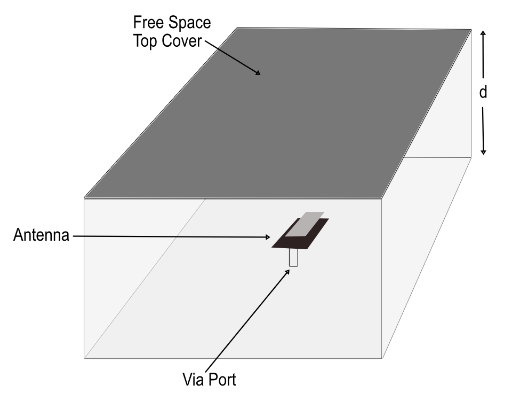
Antenna Example
A dual-band patch antenna is illustrated conceptually below. The antenna is fed with a Via Port (see Via Ports) connected between the bottom cover and the antenna. The top cover is set to Free Space and the total distance between the top and bottom covers, "d", is set to one-half wavelength and the box sidewalls are several wavelengths from the antenna.
 The example stackedpatch is an antenna similar to the one above and may be accessed using the Example Browser.
Viewing Far Field Patterns
After an EM simulation is complete, you may display a far field pattern of your antenna. The pattern is based on the current distribution data generated by the EM solver. To generate the current distribution data, enable the Compute currents option (Circuit > Settings > [EM Options]) in your project prior to analysis. See Far Field Patterns - Overview for information on plotting far field patterns.
Modeling a Matched Waveguide Load
The sidewalls of the Analysis Box can be thought of as forming the four walls of a waveguide. Therefore, Sonnet may be used to simulate a circuit or antenna within a waveguide, where the propagation of the waveguide mode(s) is towards the top or bottom cover of the Analysis Box. This can be useful for applications such as microstrip-to-waveguide transitions or waveguide simulators (used to model infinite arrays).
Providing a termination for the end of the waveguide requires a little more thought. Any waveguide mode can be perfectly terminated by making the impedance of one or both box covers equal to the conjugate of the waveguide mode impedance. This can be done automatically at all frequencies and all modes by selecting Circuit > Settings > [Box] : [Covers] and selecting WG Load from the Conductor drop-down list.
See Also