Via Ports
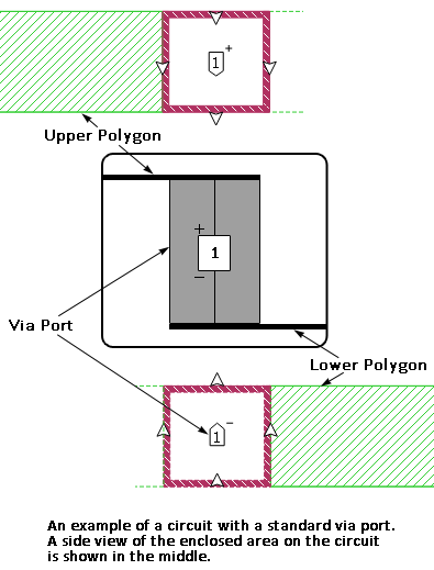
A Via Port is a special type of port that is attached to a via. It has the negative terminal connected to one end of the via polygon and the positive terminal connected to the other end. An example of this port type on a via polygon is shown below.
Unlike all other ports, the EM solver does not de-embed Via Ports or apply a reference plane. However, in a circuit which contains a combination of Via Ports and other port types, the other port types can still be de-embedded. The EM solver will automatically identify and de-embed all of the other ports present in the circuit, but skip de-embedding the Via Ports.
In most cases where you need a grounded internal port, first consider using a Co-calibrated port (as discussed in Co-calibrated Internal Ports), since Co-calibrated ports are accurately de-embedded. However, a Via Port should be used if you wish to include the inductance of the via used to feed your circuit. The example file stackedpatch has an example of a Via Port used in a patch antenna. This example file may be accessed using the Example Browser
Creating a Via Port
To create a Via Port, you must first create a via. The via can be an Edge Via or a via polygon. Once the via is in place, select Insert > Port and then click on the via to which you wish to add the Via Port.
Via Port Properties
To view or modify the properties of a single port, double-click the port. To modify multiple ports, select the ports and select Object > Port Properties. This opens the Port Properties dialog box. A description of each Via Port property is given below.
Port number: indicates the number of the port. If more than one port was selected, then the text <Mixed> appears. Ports are required to be in sequential order with no numbers missing. If you have deleted some ports such that your ports are no longer sequentially numbered, you may automatically renumber all of your ports. See Non-sequential Port Numbers for details. Port numbers are usually a positive integer, but may be negative or zero (see Special Port Numbering).
Terminal Orientation Section
These two radio buttons allow you to specify to which polygon the negative and positive terminals of the port are attached. The radio buttons and their effect is illustrated below.
Termination Section
S-parameter values, current density plots, and far field patterns depend on the port normalizing impedance, also called the port termination. The default port termination is 50 ohms. See Port Termination Impedance for more details.