Properties Common to All Port Types
Adding Ports in Sonnet's Project Editor
When you are editing your circuit in the Project Editor, you add ports by selecting the menu command Insert > Port or by clicking the Port button in the Insert toolbar. Holding down the Shift key when you select the command allows you to add multiple ports. By default the software automatically determines the type of port based on the location in the circuit. Alternatively, you may also choose the type of port to add using the Add Port drop-down list found in the Modes toolbar when adding a port.
After a port is added to the circuit, you may change the port type and port properties by double-clicking on the port, or selecting the port then selecting Object > Port Properties.
Port Termination Impedance
S-parameter values depend on the port normalizing impedance, also called the port termination impedance. In addition, current density plots and far field patterns depend on the port termination impedances used. The default port termination impedance is 50 ohms. In rare cases, you may wish to have S-parameters normalized to some other impedance. However, be aware that some analysis tools only accept the value of 50 ohms as the normalizing impedance. You may specify the port's resistance, reactance, inductance, and capacitance as shown in the diagram below.

The normalizing impedances are ignored for Y- or Z-parameters. Y- and Z-parameters are always normalized to one ohm.
Changing Port Terminations
You may change your port terminations before or after you simulate:
- Project Editor: When you change the port terminations in the Project Editor, all S-parameter output files will use these values. In addition, all graphs, plots, and patterns will use these values as their default values. There are two methods for changing the port terminations using the Project Editor. You may select the port and select Object > Port Properties or you may select Circuit > Settings > Ports.
- Graphs: Changing the port terminations in a graph does not affect the project file, nor other graphs, plots or patterns. It only affects the present graph. To change the port terminations in a graph, select Graph > Graph Options > [Terminations].
- Current Density Plots: Changing the port terminations in a current density plot does not affect the project file, graphs, other plots or patterns. It only affects the present plot. To change the port terminations in a current density plot, select Plot > Ports.
- Far Field Patterns: Changing the port terminations in a pattern does not affect the project file, graphs, plots or other patterns. It only affects the present pattern. To change the port terminations in a far field pattern, select Graph > Calculations > Ports.
Special Port Numbering
All ports are assigned a number. There is no limit on the number of ports and the number of ports has a minimal impact on the analysis time, mostly affecting the time required for de-embedding. By default, all ports are positive and unique. However, there are some applications that require the ports to have duplicate, and even negative, numbers. Ports may also be assigned multiple port numbers. There is also a special case of Port 0 which is used for a ground connection. The following section provides details on applications requiring special port numbering.
Ports with the Same Number
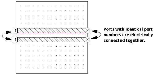
All ports with the same number, as pictured below, are electrically connected. As many physical ports as desired may be given the same numeric label. Such ports are common mode ports (sometimes referred to as even-mode or push-push ports) and have many uses, including simulating the common-mode response of a circuit.
See Interpreting Z0 and Eeff for important information on obtaining valid transmission line parameters from Sonnet.
Ports with Negative Numbers
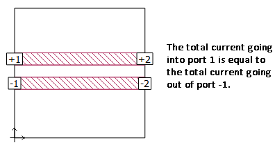
Ports may also have negative numbers as shown in the figure below. This feature can be used to redefine the ground reference of a port. Strictly speaking, the EM solver sums the total current going into all the positive ports with the same port number and sets that equal to the total current going out of all the ports with that same negative port number. For example, for a circuit with a +1 port and a -1 port, the EM solver sets current flowing into port +1 to be equal to the current flowing out of port -1. These are differential mode ports (sometimes called balanced, push-pull or odd-mode ports). An example is shown below.
Another way to think about negative ports is in terms of the ground reference for the positive port. Whenever a positive port has a corresponding negative port, the ground reference for the positive port is no longer the Analysis Box. The negative port(s) becomes the ground reference.
See Interpreting Z0 and Eeff for important information on obtaining valid transmission line parameters from Sonnet.
Modeling Coplanar Waveguide (CPW) ports use negative port numbers as shown below.

Single Port with Multiple Numbers
There are certain situations where you may wish to have two ports in the same location. For example, you may have a polygon which functions as a ground reference for two different ports. To accommodate this situation, you may include more than one port number for a given port. Just enter the port numbers separated by comma(s).
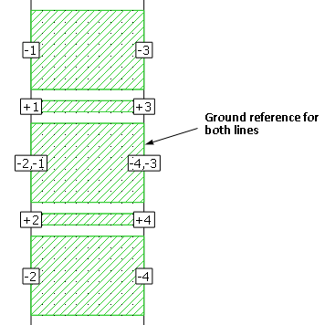
In the example below, there are two CPW through lines. The left side of the top CPW line requires a combination of -1, +1 , -1 ports, and the left side of the bottom CPW line requires a combination of -2, +2, -2 ports. The ground metal in the middle functions as a ground reference for both lines, and thus needs to be labeled -1 and -2.
Whenever a single port has two or more numbers, Sonnet electrically connects the ports together (i.e., they have the same voltage). Note that a + sign is automatically added to the positive port number when the negative port number is entered; you do not need to enter it.
Ground Connections
Setting a port number to 0 allows you to add connections to ground that are de-embedded. The main application of this feature is to allow you to add an ideal short circuit to your circuit in locations other than the Analysis Box sidewall as shown in the picture below.
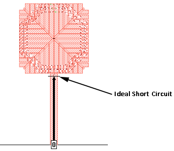
In the example above, a box-wall port with a reference plane was used to create an ideal short circuit at the edge of a patterned ground shield. Assigning the port number 0 sets the port to be an ideal short circuit, and the reference plane is used to shift the short circuit to the desired location.
All ports with the number “0” are treated as a normal port during the main part of the EM simulation. These ports are de-embedded in the same manner as all other ports. When the simulation for a particular frequency is completed, the EM solver automatically shorts all ports with the number 0 to ground. This means that the effects of the port are de-embedded without creating extra ports in your S-parameter results.
All port types can be set to 0.
Changing Port Numbering
You can use the Project Editor to change the port number of any port after it has been added to your circuit. Any integer, zero, negative or positive, is valid. See the sections above for applications where a zero or negative port number is appropriate. To change the number on a port or ports, select the port(s) and select Object > Port Properties.
Note that if multiple ports are selected, all are set to the number input in the dialog box.
Non-sequential Port Numbers
Ports are required to be in sequential order with no numbers missing. If the ports are not in sequential order, you will receive an error message when you attempt an analysis. If you have non-sequential ports, you can either manually change the port numbers to make them sequential or allow Sonnet to automatically renumber all your ports to force them to be sequential. To have sonnet do this automatically, select Circuit > Settings > [Ports] in the Project Editor, then click the Renumber button. If you have ports with duplicate numbers, you will be asked if you wish to keep the duplicates or renumber them.
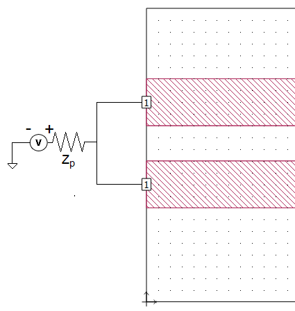
Common Mode Configuration
To model the common mode in Sonnet, two ports using the same port number should be used, as shown below. All ports with the same number are electrically connected together. As many physical ports as desired may be given the same numeric label. In the picture below, Zp is the impedance (port termination) of the port.
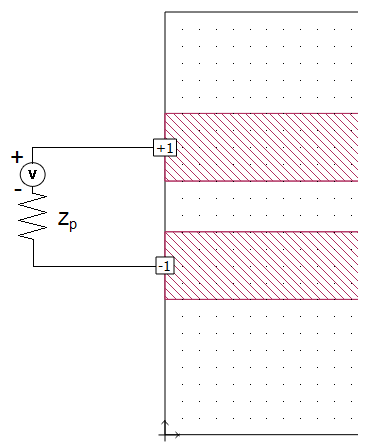
Differential Mode Configuration
To model the differential mode in Sonnet, two ports using the same port number, one positive and one negative, should be used as shown below. The EM solver sums the total current going into all the positive ports with the same port number and sets that equal to the total current going out of all the ports with that same negative port number. For example, for a circuit with a +1 port and a -1 port, the EM solver sets the current flowing into port +1 to be equal to the current flowing out of port -1. These are differential mode ports (sometimes called balanced, push-pull or odd-mode ports). In the picture below, Zp is the impedance (port termination) of the port.
CPW Mode Configuration
To model coplanar waveguide (CPW) excitations in Sonnet, use three ports, one positive and two negative, as shown below. The EM solver sums the total current going into all the positive ports with the same port number and sets that equal to the total current going out of all the ports with that same negative port number. In the picture below, Zp is the impedance (port termination) of the port.
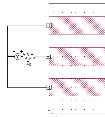
See Coplanar Waveguide (CPW) for a detailed discussion of modeling CPW in Sonnet.
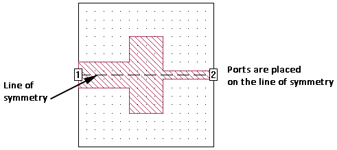
Port Placement with Symmetry On
Symmetry can be used to considerably reduce the amount of memory and processing time required to analyze a circuit which is symmetrical about the mid-line of the box. When symmetry is enabled, everything below the line of symmetry is ignored, and all metal above the line of symmetry is reflected about the symmetry line. Special care should be given to ports when using symmetry.
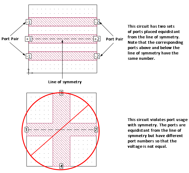
Normally, if you are using symmetry, ports are placed on the line of symmetry as pictured below.
Ports can be placed off the line of symmetry, but the port placed above the line of symmetry must have another port equidistant from and below the line of symmetry. These two ports must also have the same port type, port number and properties. The basic premise of symmetry is that the voltage at any given point above the line of symmetry must be equal to the voltage at the corresponding location below the line of symmetry. Using the same port number, port type and properties ensures that the voltage is the same at both required points.
Reference Planes
Box-wall and Co-calibrated ports can have reference planes associated with them. See Shifting Reference Planes for an explanation of Reference Planes.
See Also