De-embedding Overview
Introduction
De-embedding is the process of calibrating the ports and shifting reference planes, similar to calibrating the probes or connectors of an RF measurement and shifting the reference planes to the device under test (DUT). Sonnet de-embedding is enabled by default, and in most cases, is not a concern for the user. However, understanding the inner workings of the de-embedding process can be helpful to maintain accuracy, improve efficiency, or perhaps solve a de-embedding warning condition.
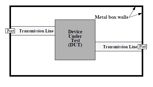
The figure below illustrates the general layout of a circuit to be analyzed by Sonnet. The DUT, shown as a gray rectangle in the figure, is the circuit for which we wish to obtain analysis results. The DUT is connected to one or more ports. The ports may be located on walls of the Analysis Box, as in the figure, or in the interior of the Analysis Box (see Introduction to Ports for a description of port types available in Sonnet). Typically, transmission lines, or "feedlines" are necessary to connect the ports to the DUT.
When de-embedding is enabled, the EM analysis performs the following sequence of steps:
- It calibrates the ports by negating port discontinuities.
- Optionally, it shifts reference planes by negating the lengths of feed transmission lines.
- For most circuits, it calculates the effective dielectric constant (Eeff) and characteristic impedance (Z0) of the feed transmission lines.
Sonnet uses a Short Open Calibration (SOC) technique to de-embed Box-wall and Delta Gap ports and uses a custom technique to de-embed Co-calibrated internal ports. For the published theory of the de-embedding techniques used by Sonnet, please see the De-embedding and Port Calibration section of the Sonnet References help topic.
Calibrating the Ports
Each port in a circuit introduces a port discontinuity into the analysis results. In addition, any feed transmission lines that might be present introduce phase shift, and possibly, impedance mismatch and loss. Depending upon the nature of your analysis, this may or may not be desirable.
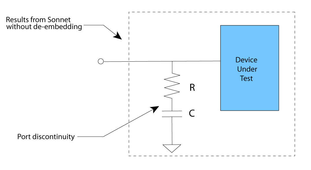
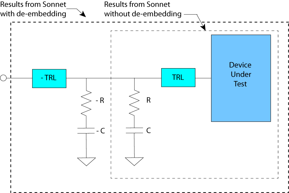
For Box-wall ports, the discontinuity is caused by the port subsections interacting with the Analysis Box wall. For internal ports, subsections are added to provide the port ground reference. The equivalent circuit for a Sonnet Box-wall Port discontinuity is a shunt RC, as shown in the figure below. The discontinuity for the other types of ports may be different, but the process outlined below is similar for all port types which can be de-embedded.
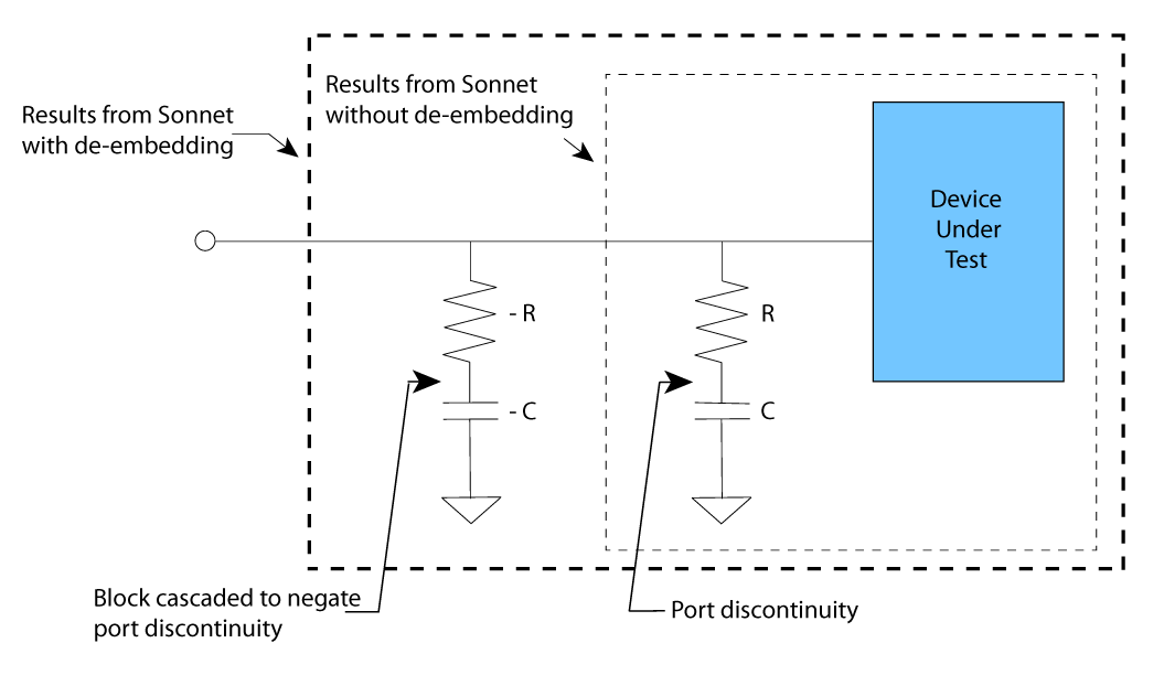
 When enabled, the de-embedding algorithm calculates the values of R and C for each box-wall port present in the circuit. The port discontinuities are then negated by cascading a negative R and C as illustrated below.
When de-embedding is enabled, both de-embedded results and non-de-embedded results are saved with the project. When graphing a project, you may plot either the de-embedded or non-de-embedded results, but the default is to plot de-embedded results.
Shifting Reference Planes
Feed transmission lines are required in many circuits to connect ports to the device under test (DUT). If the length of a transmission line is not electrically short, unwanted phase (and possibly loss) will be added to the results. If the impedance of the transmission line differs from the normalizing impedance of the S-parameters (usually 50 ohms), the results may contain an additional error. Thus, if we are only interested in the behavior of the DUT, any long feed lines connecting the ports to the DUT should be negated during de-embedding. The process of negating lengths of transmission line during de-embedding is known as shifting reference planes.
Reference planes may be specified in the Project Editor for Box-wall, and Co-calibrated ports, but not for Delta Gap and Via ports. When your circuit contains a reference plane, and de-embedding is enabled, the EM simulation automatically builds and analyzes the calibration standards necessary to de-embed the port and shift the reference plane by the specified length.
Reference planes are not necessary for de-embedding. If you do not specify a reference plane in the Project Editor, the reference plane length defaults to zero. This means that the EM simulation will not shift the reference plane for that port when de-embedding is enabled. However, it will negate the discontinuity for that port.
Simple Feed Line Example
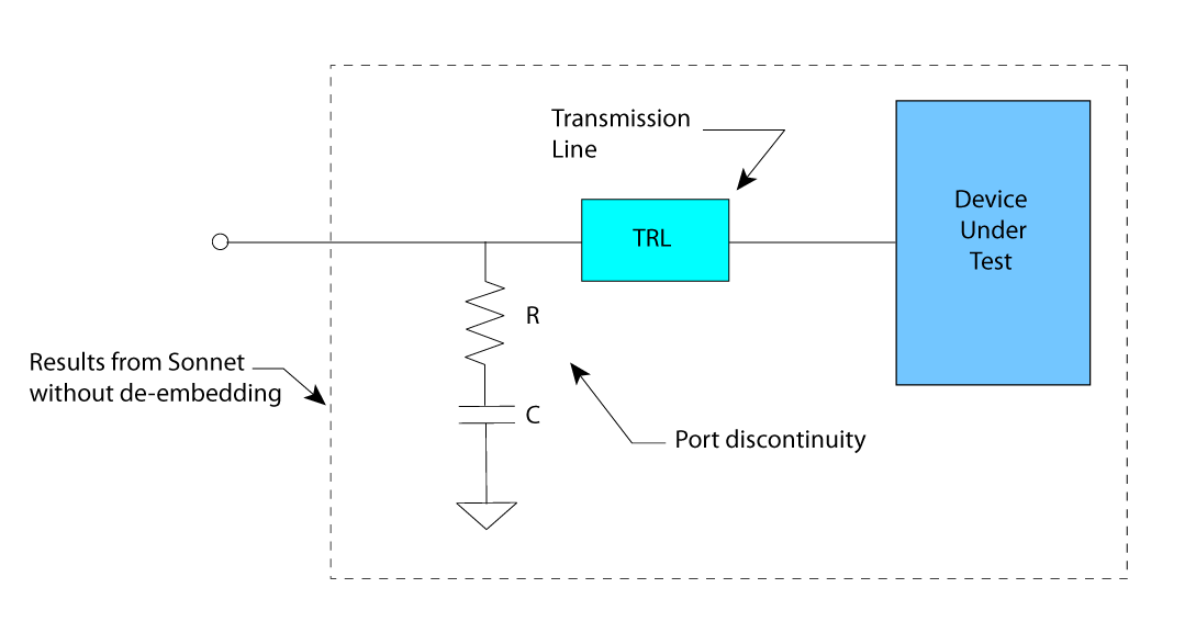
Continuing with the Box-wall port example, the figure below shows a circuit with a length of transmission line inserted between a Box-wall port and the device under test.
 When the circuit has a reference plane, the EM solver negates the transmission line in a manner similar to that used to negate the port discontinuity. It calculates results for the line alone, and then cascades a negative line along with negative R and C as illustrated in the next figure.
A Common Misconception
As explained above, a shifted reference plane negates the effects of one or more transmission lines using circuit theory after the simulation of the entire circuit. This concept is shown in the picture below.
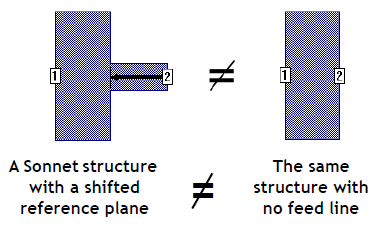
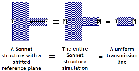 Notice that reference planes do not remove the transmission line metal, but only negate it. Shifting a reference plane is not the same as removing the metal from the simulation.
 A shifted reference plane does not remove the fringing fields due to the step in width. This concept is illustrated below. Note that the fringing fields still exist in the final Sonnet results after de-embedding.
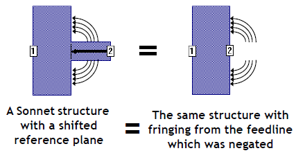
Thus, if you import these Sonnet results into a circuit simulator, the results may only make physical sense if a transmission line is connected to port 2.
The topic Shifting Reference Planes contains some guidelines for setting reference planes.
Z0 and Eeff
When a port is de-embedded, the characteristic impedance (Z0), and the effective dielectric constant (Eeff) of each feed transmission line are calculated for each discrete data point analyzed, except when any of the following conditions apply:
- The port's reference plane is diagonal.
- The port shares a reference plane with another port, including a zero-length reference plane. See the Short Reference Planes section of the Shifting Reference Planes topic for more information on sharing reference planes.
The topic Z0 and Eeff contains a more complete description and some examples.
Enabling/Disabling De-embedding
By default, de-embedding is enabled. To enable or disable de-embedding using the Sonnet Project Editor, select Circuit > Settings > [EM Options]. In the Advanced Options section, select or unselect the De-embed checkbox.