Shifting Reference Planes
If you are unfamiliar with how Sonnet treats reference planes, please read the section Shifting Reference Planes in De-embedding Overview before reading this topic.
To set the reference plane for a Box-wall or Co-calibrated port using the Project Editor, double-click the port or select the port and select Object > Port Properties. This opens the Port Properties dialog box which contains a Reference Plane section where you can use the mouse or enter the length using the keyboard.
Reference planes are ignored if the De-embed checkbox (Circuit > Settings > [EM Options])is not selected.
Guidelines
Sonnet places very few restrictions on the reference planes which may be defined for a given circuit. This is done intentionally so as to provide maximum flexibility for all users. However, there are some basic guidelines concerning reference planes that should almost always be followed. These guidelines are discussed below:
Feedlines Must Be Transmission Lines
The first guideline is to ensure that your feedlines are true TEM or quasi-TEM transmission lines. This means the following:
- Feedlines must be of uniform width across the entire distance which the reference plane covers.
- Feedlines must not over-mode. De-embedding assumes only one mode of propagation per port.
- The feedline(s) must not have an unusually high amount of loss. The metal must be conductive enough to allow power to reach the other side of the line. In addition, the dielectric must be resistive enough so the power is not shorted to ground before it reaches the other side.
Short Reference Planes
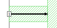
Short reference planes can cause problems with your de-embedded results. If the reference plane for a port is very short relative to the substrate thickness or the width of the feed transmission line, Sonnet may generate poor de-embedded results. This is due to one or both of the reasons discussed below.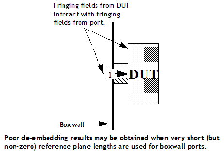 As shown above, the port is too close to the device under test (DUT). There are fringing fields associated with the port and separate fringing fields associated with the DUT. If the port and DUT are too close, the fringing fields interact. The de-embedding algorithm is based on circuit theory and cannot handle this fringing field interaction. This problem can occur with Box-wall or Co-calibrated ports. However, technically speaking, the problem is not with the short reference plane but the problem is that the DUT is too close to the port.
The other possible problem is that the calibration standard is too short. The calibration standard must be long enough such that the currents on the line(s) behave like standard transmission line(s). Since the calibration standard length for a Box-wall port is based on the reference plane length, a short reference plane can result in inaccurate results. For more details about this problem, see Calibration Standard Length.
There is no precise rule as to how long a Box-wall port’s reference plane must be made in order to prevent the above problem. The required length is dependent upon the circuit geometry and the nature of the analysis. However, we recommend that you use reference planes equal to or greater than several times the distance to the nearest ground metal. This is sufficient for most types of analyses.
Reference Planes Longer than the Feedline
Generally, reference planes should not be longer than the feedline attached to the port. This is because a reference plane is negating a transmission line. Thus if your reference plane is longer than your feedline, you are effectively attempting to negate a part of a transmission line which does not exist. Doing so may result in non-physical results such as gain in a passive circuit or non-causal results.
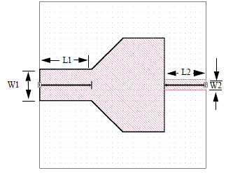
To illustrate this problem, consider the valid circuit shown below. In this circuit, the reference planes are the same length as the feedlines. When de-embedding is enabled, the Port 1 discontinuity is negated along with a transmission line of width W1 and length L1. Similarly, the Port 2 discontinuity is negated along with a transmission line of width W2 and length L2. The de-embedded result is for the block in the middle of the circuit which is usually the desired result.
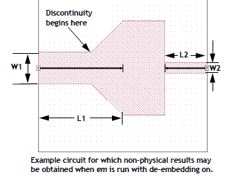
 Now, consider the figure below. This circuit is identical to the circuit shown above except that the length of the reference plane associated with Port 1 has been increased. If the EM solver is run with de-embedding enabled on this circuit, it negates a length of transmission line equal to the specified reference plane length. This occurs even though the actual feed transmission line is shorter than the reference plane length. As a result, the de-embedded results may be non-physical (i.e., the results may not obey the laws of physics by being non-passive or non-causal).
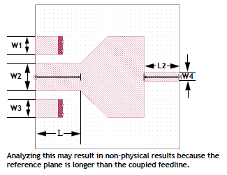
 A second de-embedding example leading to non-physical results is shown in the next figure. In this example, the circuit has two via pads on each side of the port transmission line.
When the EM solver is run with de-embedding enabled on this circuit, it negates three coupled feedlines with a length equal to the reference plane length. Since the reference plane extends from the box wall beyond the vias, the de-embedded results may be non-physical.
De-embedding Without Reference Planes
Reference planes are optional for Co-calibrated, and Orthogonal Box-wall ports but are required for diagonal Box-wall ports. If you do not specify a reference plane for a Co-calibrated or Orthogonal Box-wall port, de-embedding will still remove the discontinuity associated with the port.
As discussed in Short Reference Planes, Sonnet may generate poor de-embedded results if you attempt to use a very short (but greater than zero) reference plane for a Box-wall port. However, if you de-embed without a reference plane, Sonnet will use a longer calibration standard which avoids this problem. Therefore, we recommend that you de-embed without a reference plane rather than specifying a very short, non-zero, reference plane length for Box-wall ports. No such restriction applies to Co-calibrated ports since their calibration standard length does not depend on the reference plane length.
Coupled Transmission Lines
Sometimes, your circuit may contain multiple parallel feedlines as shown in the circuits below.
There are two problems in the above examples which are solved by de-embedding:
- The ports are close to each other. When ports are close to each other, their fringing fields can couple to each other. If the ports are not calibrated at the same time, this would result in errors.
- The feedlines are close to each other. When feedlines are close to each other, they can couple to each other. If you are using reference planes, this coupling between the feedlines needs to be removed.
Both of these issues are resolved by using Shared reference planes. When the reference planes are Shared, coupled lines are used for calibration standards, thus removing the coupling between the ports and the feedlines. The alternative to Shared reference planes is Independent reference planes.
Shared Reference Planes
When ports have shared reference planes:
- The length of each reference plane is the same.
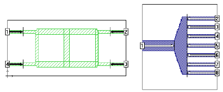
- Calibration standards are composed of multiple coupled lines as shown below.
- Coupling between the fringing fields of the ports is removed to provide a more accurate result.
- Coupling between feedlines is removed over the entire length of the reference plane.
- Sonnet does not calculate a characteristic impedance (Z0) or effective dielectric constant (Eeff). This is because the lines are treated as coupled and coupled lines have multiple Z0 and Eeff values.

There are only two types of ports which can have shared reference planes:
- Orthogonal Box-wall ports: Only ports on the same box wall may be shared. Orthogonal box-wall ports share reference planes by default but can be changed to be Independent.
- Orthogonal Co-calibrated ports with a Box Cover or Polygon Plane Ground Reference: Ports in the same calibration group always share a reference plane. See Co-calibrated Internal Ports for more information on how to ensure Co-calibrated ports belong to the same calibration group.
Independent Reference Planes
When ports have independent reference planes:
- The length of each reference plane may be set independently.
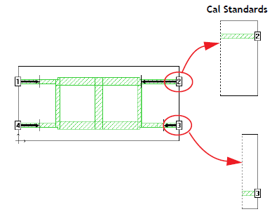
- Calibration standards are composed of single (uncoupled) lines as shown below.
- Coupling between the fringing fields of the ports is not removed. Thus, ports must be far apart to ensure an accurate result.
- Coupling between feedlines is not removed. Therefore, you should not use independent reference planes when the lines are close enough to couple.
- Sonnet calculates a Z0 and Eeff for each feedline without the influence of the nearby lines.
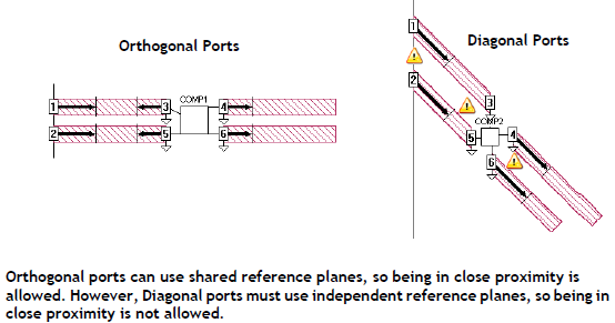
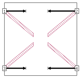
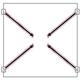
 Diagonal box-wall ports, and diagonal co-calibrated ports are always independent. Thus, they should not be used if the ports or feedlines are close to each other. This concept is shown below.
 Orthogonal box-wall ports may be set to Independent or Shared. To change a Box-wall port from shared to independent using the Sonnet Project Editor, double-click the port, expand the Advanced section, and click the Independent reference plane length radio button.
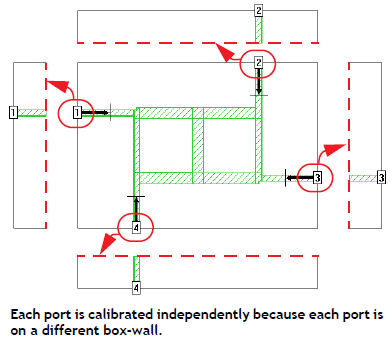
Ports on different box-walls are always treated as independent from one another as shown below.
Diagonal Reference Planes
For some designs, feedlines do not lie in either the x or y axis, but extend diagonally from the port. In this case, if the port is Orthogonal, the reference plane does not extend along the feedline, so that the feedline effects are not removed correctly in the de-embedding process. An example is shown below.
The solution to this problem is to use diagonal reference planes. The method to do this depends on the port type as explained below.
Box-wall ports: For Box-wall ports, a reference plane must be defined as Independent in order to use a diagonal reference plane. To change a Box-wall port from shared to independent using the Sonnet Project Editor, double-click the port, expand the Advanced section, and click the Independent reference plane length radio button. Once it has been set to Independent, select the Allow the reference plane to be diagonal checkbox. This allows the reference plane to extend along the polygon to which the port is attached as shown below.
Co-calibrated ports: For Co-calibrated ports, reference planes are always perpendicular to the polygon edge to which the port is attached. Thus, any port on a diagonal edge will have a diagonal reference plane.

Component Ports: Since Components use Co-calibrated ports, the rules for Component Ports are the same as for Co-calibrated ports (see above).
Sonnet does not calculate the characteristic impedance (Z0) or the effective dielectric constant (Eeff) for ports with diagonal reference planes.
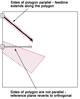
Non-Uniform Line
When using a diagonal reference plane, it is important to ensure that the two sides of an angled polygon are parallel to each other. The angle of the two polygon edges extending from the port are used to determine the angle of the reference plane. If the angles are different, the setting becomes ambiguous and the reference plane reverts to being orthogonal.
Fixed vs. Linked Reference Planes
When you create or edit a Box-wall port, you may define a reference plane to be either Fixed or Linked.
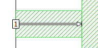
- Fixed: Fixed reference planes are a constant length and do not change when polygons are reshaped or moved (such as may occur when a Dimension Parameter changes value). A Fixed reference plane is indicated by a black arrow.
- Linked: Linked reference plane are linked to a point in a polygon. If that point moves, as part of a reshape or a new value for a parameter, the length of the reference plane also changes. A Linked reference plane is indicated by a white arrow with a black outline.
Fixed Reference Plane
Linked Reference Plane
Linked reference planes are only supported for Box-wall ports that are not set to be Independent.