Co-calibrated Internal Ports
Co-calibrated ports are the most used internal port type, due to their flexibility in positioning and ground reference. They utilize a high accuracy, Generalized Local Ground (GLG) de-embedding technique [16] that removes all port-to-port coupling within a Port Group, during the EM analysis. A typical usage of Co-calibrated ports is to provide attachment points for circuit elements (RLC, data file, etc.) in a subsequent circuit theory analysis tool such as Keysight ADS, Cadence AWRDE, Cadence Virtuoso, or Sonnet's netlist solver.
Calibration Groups
A Co-calibrated port is always associated with a calibration group. A calibration group uses a common ground reference. During an EM analysis, the Co-calibrated ports within a group are simultaneously de-embedded. As a result, all coupling of the fields introduced by the ports is removed.
By default, Co-calibrated ports which are in reasonable proximity and share the same Ground Reference are automatically grouped (see Restricted Space for exceptions). If you wish to observe the grouping determined by the software before running your analysis, you may select the command View > View Subsections from the Project Editor main menu.
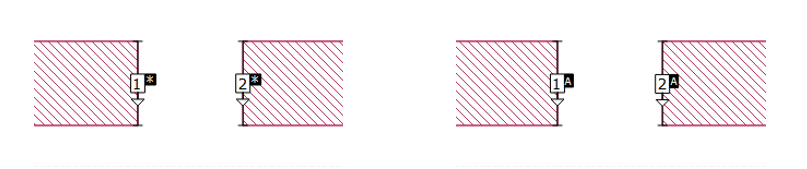
Also, It is possible to manually define a calibration group which overrides the automatic settings. The picture below shows an example of the port symbols used when automatic grouping is enabled (left picture) and when the ports have been manually grouped into a group labeled "A" (right picture).
To manually group two or more ports into the same calibration group, select the ports, then use Object > Port Properties to select a new or existing Calibration group name from the Calibration group name drop-down list.
Ports on different metal levels may be grouped together into a single group.
Ground Reference
You must define how the common ground reference of your calibration group is connected to your circuit. There are four choices for ground reference: Auto, Box Cover, Polygon Plane and Floating which are explained below.
Auto Ground Reference
When the ground reference is Auto, the software determines where to place the ground reference. The type of ground reference used is indicated by the port symbol (see Port Symbols).
Box Cover Ground Reference
When the ground reference is defined as Box Cover, all Co-calibrated ports in the group are globally grounded to one or both box covers of the Analysis Box. To do this, the analysis automatically creates a via which connects to the cover(s). The effects of the via are negated by the de-embedding algorithm.
You should choose this option if the element model or measured data to be connected to these ports includes shunt elements to ground. Examples of elements where you would use Box Cover ground reference include:
- S-parameter data that includes pads or other coupling to ground.
- Transistor data that includes a via to ground in the model/measurement.
This type of Co-calibrated port is illustrated below. The positive terminal is attached to a polygon edge of a feedline and the negative terminal is attached to a via to ground which is negated during de-embedding.
When Box Cover is selected as the ground reference, you also select a ground direction. If the ground direction is set to Auto, the software automatically determines the most efficient direction the ground via should extend taking into consideration the distance, the electrical properties of the dielectric layers between the port and the box covers, and the loss of the box top or bottom cover. The selected direction is shown in the port symbol as illustrated in the Port Symbols section of this topic. You may also select the top cover by selecting Above, or the box bottom by selecting Below. When using this type of ground direction, you must make sure that there is a clear path with no metal on other levels interfering with the path to the chosen box cover.
The box cover being used as a ground reference should be low loss. For example, you should not use Free Space for the cover that is used for the ground reference. In addition, any dielectric between the port and the box cover being used as the ground reference should be low loss.
Floating Ground Reference
When the ground reference is defined as Floating, all Co-calibrated ports in the group are connected to a common ground but not to the Analysis Box. Instead, the ground reference is left unconnected to the rest of your circuit. You should choose this option if the element model or measurement data that will be connected to these ports does not have a ground reference or does not have shunt elements. Examples of this are:
- A series RL equivalent circuit
- Surface-mount device S-parameter data that was measured/modeled without any pads or the pad capacitance was mathematically removed from the measurement.
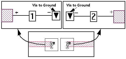
This type of Co-calibrated port is illustrated below. The EM analysis automatically adds extra metal which connects all Co-calibrated ports in a calibration group. This extra metal is defined as Generalized Local Ground (GLG) metal since it acts as a local ground for the ports in the calibration group. The positive terminal of a Co-calibrated port is attached to a polygon edge of a feedline and the negative terminal is attached to GLG metal. During the de-embedding process the effects of this additional metal are removed.
When a circuit contains Co-calibrated ports with a Floating ground reference and other ports with a different ground reference (such as Box-wall ports or other Co-calibrated ports), the Sonnet results may not make sense to the casual observer because the ports do not share a common ground reference. We recommend refraining from viewing your results until after you have connected your device(s) to your ports such that all remaining ports share a common ground reference.
You may not set a reference plane for a Co-calibrated port if your Ground Reference is Floating.
Polygon Plane Ground Reference
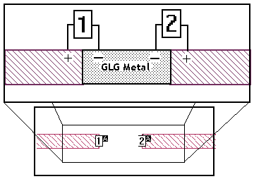
When the ground reference is defined as Polygon Plane, all Co-calibrated ports in the group use a polygon on another level as the ground reference. The ground reference for the Co-calibrated port is attached to the first polygon encountered in the direction specified for the ground reference. When using this type of ground reference,
- There should be a clear path with no metal on other levels interfering with the path to desired ground plane polygon.
- The ground reference polygon should be several times larger than the width of the polygon to which the port is connected.
- The polygon being used as a ground reference should be low loss.
This type of ground reference is illustrated below.
Upper level showing signal
line and port
Lower level showing polygon
plane and ground symbol
The polygon being used as a ground reference should be low loss. In addition, any dielectric between the port and the ground polygon should be low loss. The polygon should also be large enough to be used as a ground plane.
Viewing the GLG Metal
To observe the GLG metal for any type of ground reference, you may select the View > View Subsections command in the Project Editor. When the Subsection Viewer appears, select View > GLG Metal from the Subsection Viewer’s main menu.
Port Symbols
The port symbol used in the Project Editor indicates the type of ground reference as shown in the table below.
| Symbol | Ground Reference |
| Box Cover - Above | |
 |
Box Cover - Below |
 |
Box Cover - Both |
| Polygon Plane - Above | |
 |
Polygon Plane - Below |
 |
Polygon Plane - Above and Below |
 |
Floating |
Restricted Space
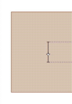
When Co-calibrated ports share the same calibration group, they form an imaginary rectangle, called the "restricted space", between them. The dimensions of the restricted space are set by the Terminal Width of each port as illustrated below. For the best possible accuracy, no objects should be present in the restricted space, even on layers above or below the port layer.
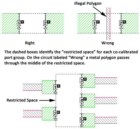
In addition, avoid using objects in close proximity to the restricted space, even if outside the restricted space. An example is shown below.

In addition, multiple ports on the same side of the restricted space should be aligned. In the illustration below, the Co-calibrated ports on the left are placed incorrectly. Ports 1 and 3 will not be grouped and will lead to inaccurate results. The ports on the right are placed correctly.

Co-calibrated ports on multiple levels that belong to the same group must also be aligned.
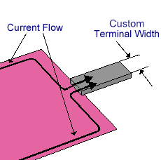
Terminal Width
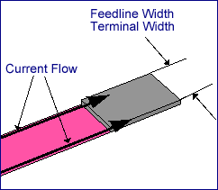
The Terminal Width of a Co-calibrated port is the electrical contact width of the component which will be attached to it later. This allows the current flow from the circuit geometry to the component to be accurately modeled. There are three choices for Terminal Width: Feedline Width, One Cell, and Custom.
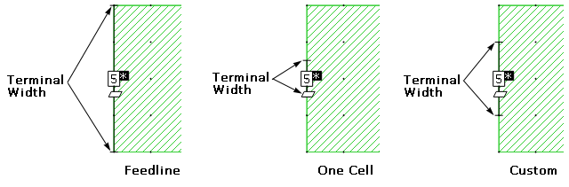
Feedline Width: This defines the Terminal Width as equal to the width of the feedline to which the Co-calibrated port is attached. This is illustrated below. Notice that there is no discontinuity in the current between the feed line and the port.
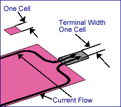
One Cell: This defines the Terminal Width to be the smallest possible width (one cell wide) as pictured below. Notice the discontinuity in the current between the port and the feed line. This discontinuity is intentionally not removed during de-embedding.
Custom: This allows you to enter any desired value for the Terminal Width. This type of Terminal Width is shown below.
The Terminal Width is indicated in the Project Editor by a black line with a "T" at either end as pictured below for all three options.
Diagonal Feedlines
A Co-calibrated port may be connected to a diagonal feedline as illustrated in the left picture below. However, coupling between multiple diagonal feedlines is not removed by the de-embedding algorithm. Therefore, you should avoid closely spaced diagonal feedlines connected to Co-calibrated ports. An example of such a case is shown in the right picture below.

Reference Planes
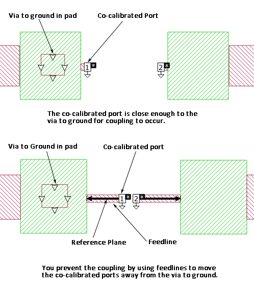
It can often be helpful to add a feedline to a Co-calibrated port, then use a reference plane to negate the length of the feedline. This allows you to place the port and any ground reference via far enough away from other circuit elements to prevent coupling.
In the illustration below, the top circuit places the Co-calibrated port close enough to the via in the pad for coupling to occur. In the bottom circuit, feedlines have been added to move the Co-calibrated ports further away in order to prevent any coupling to the via. Reference planes are set for the Co-calibrated ports to remove the effects of the feedlines during the de-embedding process.
You may not set a reference plane for a Co-calibrated port if your Ground Reference is floating.
For a detailed discussion of how reference plane and calibration standard lengths are used during the de-embedding process, please refer to Calibration Standard Length and Shifting Reference Planes.
Simplified Co-Calibrated Ports
A Simplified Co-calibrated port is a special case of a Co-calibrated port that has the positive terminal attached to the edge of a metal polygon located inside the box and the negative terminal attached to one or both Analysis Box covers. In addition, a Simplified Co-calibrated port is never grouped with any other port. Thus, coupling between a Simplified Co-calibrated port and other ports is not removed.
In previous releases of Sonnet Software, a Simplified Co-calibrated port was called an auto-grounded port.
The Simplified Co-calibrated port is not as accurate as a normal Co-calibrated port so should only be used when necessary. There are two possible reasons you may wish to use a Simplified Co-calibrated port:
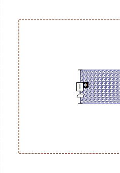
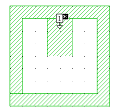
- Unlike a normal Co-calibrated port, a Simplified Co-calibrated port may be placed between two polygons. This allows you to create a port in a location without an open polygon edge. An example is shown below.
 In most circuits, the addition of Co-calibrated ports has little influence on the total analysis time of the EM analysis. However, for some circuits, Co-calibrated ports may require more time in the de-embedding phase of the analysis. In these cases, you may wish to use Simplified Co-calibrated ports, which are more efficient (but less accurate) than Co-calibrated ports.
Simplified Co-calibrated ports can attach to the edge of any metal polygon in the interior of a circuit. There are no restrictions on the loss parameters of the metal used in the polygon. However, along the edge of the metal polygon where the port is attached, the EM analysis converts the edge cells to lossless metal. For most circuits, this should have little or no effect on the results. If, however, the port is attached to a highly lossy metal polygon, such as a thin-film resistor, the edge cell(s) of that polygon will be made lossless, and the output results may be affected.
Terminations
S-parameter values, current density plots, and far field patterns depend on the port normalizing impedance, also called the port termination. The default port termination is 50 ohms. See Port Termination Impedance for more details.