Introduction to Ports
Sonnet offers a choice of several port types. You should select the port type that best suits your needs based on the following criteria:
- Location: Ports may be placed on either the interior or edge of your circuit. The required location will constrain which port types may be used.
- Ground Reference: All ports in Sonnet have a positive (or signal) terminal and at least one negative (or ground reference) terminal. The type of ground reference required will constrain which port types may be used.
- Port calibration: The ports of all EM solvers, including Sonnet's EM solver, introduce some extra parasitics. These parasitics can be removed using a port calibration technique as part of the de-embedding process. The accuracy of the port calibration depends on the port type chosen.
- Reference planes: Some ports allow reference planes while others do not.
Port Type Overview
The port types available in Sonnet are listed below, along with their unique features. For a more detailed description, click on the associated link.
- The most common type of port.
- The positive terminal is attached to a metal polygon and the negative terminal is attached to the Analysis Box wall (which is usually ground).
- The most accurate port calibration.
- Used for connections to the periphery of your geometry.
- Reference planes may be used.
- Used in the interior of a circuit.
- The ground reference can be defined as floating, the box top or bottom cover, or a polygon plane.
- Coupling between port parasitics is negated.
- Highly accurate port calibration.
- Reference planes may be used for most Co-calibrated Internal ports.
- Used in the interior of a circuit between adjacent polygons.
- The positive terminal is attached to one of the metal polygons and the negative terminal is attached to the adjacent polygon.
- Reference planes cannot be used.
- Highly accurate port calibration.
- Used in the interior of a circuit.
- Port calibration is not available.
- Reference planes cannot be used.
- Used when you want to include the inductance of the via, such as with a coax feed of a patch antenna.
Also, there are many properties that are common to all port types. See Properties Common to All Port Types for details.
Adding a Port
When you edit your circuit in the Project Editor, you may add ports by selecting the menu command Insert > Port, or by clicking on the Port button in the Insert toolbar. When you select this command, you enter Add Port mode and the Add Port toolbar appears in the project editor tab. This toolbar is only displayed in Add Port mode.
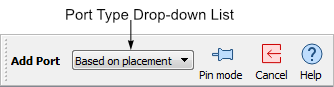
If you wish to specify the type of port you are adding to your circuit, select the desired port type from the Type drop-down list on the Add Port toolbar. By default, the type of port is automatically determined when you add the port to your circuit. The type of port that will be added in any given location is indicated by the appearance of your cursor. The table below shows the various cursors when adding a port.
| Cursor | Description |
 |
Indicates that you are in Add Port mode but are not at a location where a port may be added. |
 |
Indicates a box wall port. |
 |
Indicates a co-calibrated port. |
 |
Indicates a via port. |
 |
Indicates a delta gap port. |
After you add a port, the port type is indicated by a symbol as shown below.
| Port Symbol | Type of Port |
 |
Box wall Port: The negative terminal is connected to the box wall and the positive terminal is connected to the polygon edge. |
 |
Co-calibrated Port: In this example the down arrow indicates that the ground reference is the box bottom and the * indicates it is auto-grouped. |
| Via Port: The first symbol indicates the top of the via port and the second the bottom of the via port. The polarity is indicated by the "-" and "+" signs. | |
 |
Delta Gap Port: The polarity is indicated by the "-" and "+" signs. |
If you wish to add multiple ports, press the Shift key while making your menu selection, or click the Pin mode button in the Add Port toolbar. Press the Esc key to exit the Add Port mode.
Port Errors
If the port symbol is drawn in black, then the port is correctly placed. If the port symbol is drawn in red, then the port is incorrectly placed and the EM solver would issue an error if you attempt to run an analysis.
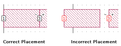
To determine what is causing the error condition, hover over the red port symbol with your mouse. A pop-up will appear to explain the error condition. Alternatively, you may right-click on the port and select "Error Message" from the pop-up menu.
Deleting a Port
To delete a port, click on the port to select it, then use Edit > Cut to delete it, click the Cut button in the toolbar, or press the Delete key on your keyboard.
Editing Port Properties
After a port is added to the circuit, you may change the port type and orientation by double-clicking on the port. Alternatively, you may select the port, then select Object > Port Properties to open the Port Properties dialog box.
If you change the type of port and it is incorrectly placed for that type of port, the port symbol will turn red.
See Also