Delta Gap Ports
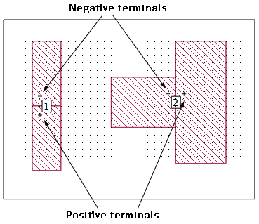
A Delta Gap port is located in the interior of a circuit and has its two terminals connected between abutted metal polygons. A Delta Gap port is illustrated below. The polarity of the port is indicated in the Project Editor as pictured below and may be reversed by changing the Terminal Orientation in the Port Properties dialog box. Delta Gap ports can be de-embedded; however, you may not set a reference plane or calibration standard length. Delta gap ports are used for similar applications as two Co-calibrated Internal Ports with a Floating Ground Reference, but they do not require any space between the two polygons as is required for a Co-calibrated port.
Delta Gap ports are not allowed on the edge of a single polygon because this would leave one terminal of the port unattached.
Care should be taken in interpreting the results for circuits which use multiple Delta Gap ports since the ports do not all share a common ground reference. Care should also be taken when using the results in a third-party circuit simulator or Sonnet netlist project because the negative terminal of a Delta Gap port is a polygon edge which is usually not your system ground.
Delta Gap Port Properties
To view or modify the properties of a single port, double-click the port. To modify multiple ports, select the ports and select Object > Port Properties. This opens the Port Properties dialog box. A description of each Delta Gap port property is given below.
Port number: indicates the number of the port. If more than one port was selected, then the text <Mixed> appears. Ports are required to be in sequential order with no numbers missing. If you have deleted some ports such that your ports are no longer sequentially numbered, you may automatically renumber all of your ports. See Non-sequential Port Numbers for details. Port numbers are usually a positive integer, but may be negative or zero (see Special Port Numbering).
Terminal Orientation Section
These two radio buttons allow you to specify to which polygon the negative and positive terminals of a port are attached. The radio buttons and their effect is illustrated below.
Termination Section
S-parameter values, current density plots, and far field patterns depend on the port normalizing impedance, also called the port termination. The default port termination is 50 ohms. See Port Termination Impedance for more details.