Box-wall Ports
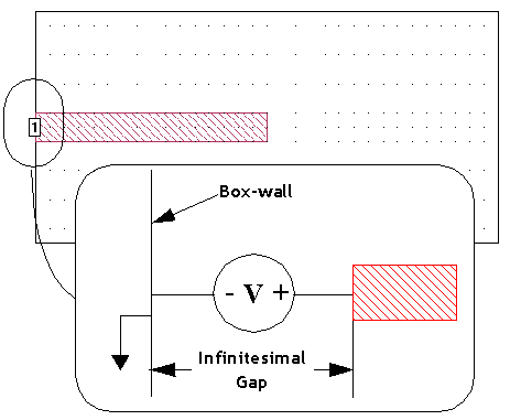
A Box-wall port is the most used port. It has one terminal attached to a polygon edge coincident with an Analysis Box wall and the second terminal attached to the Analysis Box wall. The port breaks the connection between the polygon and the wall and is inserted in an infinitesimal gap between the polygon and the wall. The positive (signal) terminal of the port connects to the polygon, while the negative terminal of the port is attached to the box wall (usually ground). Since the box wall is usually ground, this implies that the port's negative terminal is usually ground. An example of a Box-wall port is shown below.
Box-wall ports can be de-embedded and can also have reference planes. Please refer to De-embedding Overview for more information.
Box-wall Port Properties
To view or modify the properties of a single port, double-click the port. To modify multiple ports, select the ports and select Object > Port Properties. This opens the Port Properties dialog box. A description of each Box-wall port property is given below.
Port number: indicates the number of the port. If more than one port was selected, then the text <Mixed> appears. Ports are required to be in sequential order with no numbers missing. If you have deleted some ports such that your ports are no longer sequentially numbered, you may automatically renumber all of your ports. See Non-sequential Port Numbers for details. Port numbers are usually a positive integer, but may be negative or zero (see Special Port Numbering).
Reference Plane Section
The Reference Plane section contains controls for setting the reference plane of the selected port(s). See Shifting Reference Planes for a detailed discussion of reference planes.
Reference Plane type drop-down list: Select the desired way of defining the reference plane length from this drop-down list; you may choose None, Fixed, or Linked.
- None: Selecting None means that no reference plane is used. Only the port discontinuity is de-embedded. If you wish to use a calibration length for this port, select the Use fixed calibration length checkbox and enter the calibration standard length in the text entry box. See Calibration Standards for more details. The checkbox is only enabled when None is selected as the reference plane type.
- Fixed: Selecting Fixed allows you to create a reference plane that has a constant length and does not change when polygons are reshaped or moved (such as may occur when a Dimension Parameter changes value). After selecting this radio button, you may set the length one of two ways. You can enter a length in the text entry box. Alternately, you may click the Use Mouse button, then click the location in your circuit to which you wish the reference plane to extend. A Fixed reference plane is indicated by a black arrow.
- Linked: Selecting Linked links the reference plane to a point on a polygon. As that point on the polygon moves, as part of a reshape or a new value for a parameter, the length of the reference plane also changes. After selecting this radio button, you click the Use Mouse button, then click the point in your circuit to which you wish to link the reference plane. A Linked reference plane is indicated by a white arrow with a black outline.
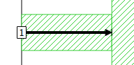
Fixed Reference Plane
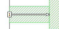
Linked Reference Plane
Advanced - Reference plane length sharing: The type and orientation of the reference plane are displayed in the Advanced section of this dialog box. For Box-wall ports, you may click the expansion arrow (>) to display the advanced settings. See Shared Reference Planes for an explanation of these settings.
Termination Section
S-parameter values, current density plots, and far field patterns depend on the port normalizing impedance, also called the port termination. The default port termination is 50 ohms. See Port Termination Impedance for more details.