The Analysis Box
The Sonnet EM analysis is performed inside a six-sided metal box as shown below.
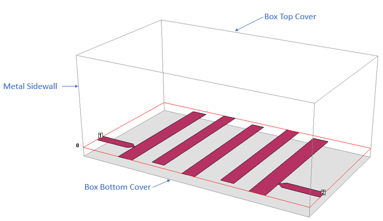
The Analysis Box is composed of four sidewalls and two covers
The four sidewalls of the box are perfect electric conductors. The top and bottom covers of the box may have any loss, allowing you to model ground plane loss or radiation. Any polygon touching a sidewall or a cover is electrically shorted to it.
Box Settings
The Analysis Box properties are set by selecting Circuit > Settings > [Box]. This opens the Box pane which includes two tabs as described below.
Box Tab
The entries in the Sizes section define the area of the box, and include Cell Size, Box Size and Num. Cells. Changing one of the entries will cause the other settings to be updated. The dialog box allows you to ”lock” any of these values while entering changes. These three values are related in the following manner:
Num. Cells * Cell Size = Box Size
where Num. Cells must be an integer.
Cell Size: This entry row defines the size of a single cell of the Analysis Box area. You enter an X dimension and a Y dimension. Selecting cell size is important. The EM analysis automatically subsections the circuit based on the cell size. Small cells result in slower but more accurate analyses. See Tips for Determining a Good Cell Size for more information.
Box Size: This entry row defines the size of the Analysis Box. You enter an X dimension and a Y dimension.
Num. Cells: This entry row defines the number of cells in the box area. You enter an X dimension and a Y dimension.
Lock Buttons: At the end of each entry row is a Lock button. Click the lock button on an entry row to prevent the values from changing when values in either of the other two entry rows change.
Recalculate: This button only appears if a Lock button is set for one of the three fields: Cell Size, Box or Num. Cells. If you enter a new value in an unlocked field, this button is enabled. Click this button to recalculate all of the fields based on any changes made to the entered values.
Symmetry: This checkbox enables Symmetry. See the Symmetry section below for more details.
Resize Box Using Mouse: Click this button if you wish to resize the box using the mouse. A rectangular outline appears with handles. You may change the box size by dragging the handles with your mouse. You may also click the Drag area button,  , which allows you to drag a new box area with your mouse. When finished, press the Enter key or click the Enter button in the toolbar.
You may also resize the Analysis Box by selecting Circuit > Resize Box.
Cell Size Calculator: Click this button to open the Cell Size Calculator which allows you to enter your critical circuit dimensions to calculate an optimal cell size.
Estimate Memory: Click this button to get an estimate of the amount of memory needed to analyze the circuit using the present cell and box size.
Symmetry
The Symmetry checkbox allows you to enable Symmetry for your circuit. By default, Symmetry is disabled. If a circuit is symmetric about the center line parallel to the x-axis, then activating Symmetry results in a 4X - 8X faster analysis and reduces the memory required from 1/4 to 1/3 of what was needed before Symmetry was enabled. When Symmetry is enabled, a horizontal dashed line representing the line of symmetry is displayed in the Project Editor. The picture below is an example circuit showing the line of symmetry.
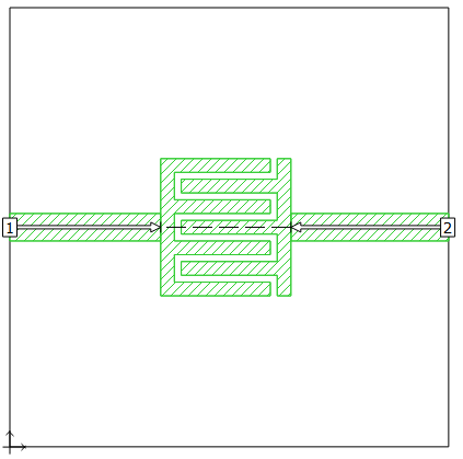
When Symmetry is enabled, all polygons below the line of symmetry are ignored, and all polygons above the line of symmetry are reflected below the line of symmetry. Therefore, you may enter just half of your circuit, making sure that you enter in the half that is above the line of symmetry.
Special care should be given to ports when using Symmetry. Please refer to Port Placement with Symmetry On for a detailed explanation of port placement when Symmetry is used.
Sonnet provides many example files which use Symmetry. In the Example Browser select Symmetry in the Feature drop-down list to see a list of Sonnet projects using Symmetry.
Covers Tab
The Covers tab allows you to define the conductor properties of the box top and box bottom. There are three predefined conductors:
- Perfect Conductor: Models a perfect electric conductor (PEC).
- Free Space: Used to model radiation or to prevent unwanted box resonances. See Antennas and Radiation and Box Resonances for details.
- WG Load: See Modeling a Matched Waveguide Load.
You may also use any conductor which you have defined.
If the metal of your top or bottom cover has a surface roughness, you may also enter those values here. Note that only the bottom surface of the top cover and the top surface of the bottom cover are relevant.